Two-level lift gate - Part 4 of 4 (final product)

 Here are pictures of the final product which works exactly as I had hoped.

The whole structure with gates in the closed position.


The whole structure with gates in the open position.


Closeup of the two linkages between the two levels (one on each side) - note the turnbuckles for fine adjustments. Each deck is made of 1/2 inch plywood with 3/4 inch angle aluminium braces down both sides which eliminate any possibility of sagging over time and provide a very robust surface on which to mount the linkages.


This is the threshold that connects the uprights on both sides.


One side of the threshold is hinged to reveal wiring that must transit from one side to the other.


This turnbuckle is used to ensure that the upright can be slightly adjusted from side to side in the event that the gates become a little too tight or too loose a fit between the two uprights.

A close up of the Lee Valley dampers.


One of the 4 Tortoise switch machines used to operate the safety barriers, mounted in position under the benchwork. The white styrene tube that is epoxied to the final drive shaft of the Tortoise is visible as is the glob of epoxy which oozed out the sides - not pretty but it works very well.


This is a 3D printed shell that covers this one Tortoise - because the Tortoise is mounted underneath a trestle I didn't want the green Tortoise to stand out. I shall add some wood siding to cover the ugly wiring.

One of the barriers in the closed position (since the upper deck is a single track the barrier swings from one side and not from the center as depicted in an earlier graphic). Note the two red LEDs which are glowing as a reminder that the gates are open. I know it is very obvious that the gates are open but the red lights tend to catch the eye while the raised gates send to blend in with the benchwork.


One of the barriers in the closed position. I will be building a finished wood structure to enclose the ugly wire, etc. underneath the LED.


These are the 4 microswitches that control the tortoise, the track power and the lights. Two of these are wired together as double-pole double-throw switches to provide reversible power to the 4 Tortoise switch machine barrier controllers. One provides track power. One provides power to the red LED warning lights. These are mounted in a 3D printed block which is mounted under the benchwork as shown. When the gate is lowered there is another 3D printed block that presses against the 4 microswitches simultaneously. This is shown in the following two diagrams.

The microswitches are pressed by the closing of the lower gate (gate is turquoise). Microswitches (4 of them side by side) are blue and the switch arm is yellow. Note this is not to scale - dimensions are exaggerated to illustrate how the mechanism works.

When the lower gate is open (turquoise) the microswitches are released.


Another shot of the completed structure.


Two-level lift gate - Part 3 of 4 (design & construction)

 Criteria 4: "Reliable track power to rails on both decks and power cutoff when gates are open."


The track is divided into three electrically separate sections for each level - the track on the gate itself (the part that lifts) and 40 cm (1.3 feet) of the track approaching the gate from each side. Each rail of all three sections is wired to a separate micro-switch which is opened and closed by the opening and closing of the gate. When the gates are closed the circuits are intact and when the gates are open the circuits are broken, cutting all power to the rails. In hindsight, I realize that the track to the gate could have been wired directly to the source of track power because one would never leave a train on the gate when it is being opened!

Here is a graphic of the track wiring, with each horizontal black line depicting a rail.


Criteria 5: "Mechanical barriers that automatically close when the gate is opened and open when the gate is closed."

I needed four physical barriers that would be closed to block trains when the gates are opened. A Tortoise Slow Motion switch machine made by Circuitron http://circuitron.com/ contains a stall motor which powers a series of reduction gears to slowly move a horizontal slider. In normal operation, the horizontal slider is attached to a piece of piano wire which passes up through a fulcrum, through the model railroad benchwork and finally through the throwbar which connects the point rails of a turnout. A stall motor is designed to be powered all the time to constantly apply force against the point rails. Such a motor has an extremely low current draw and won't burn out when it is "stalled".


By removing the last component of the drive train, the "horizontal slider" mentioned above it is possible to drill a hole in the case of the Tortoise to permit a styrene tube to pass through and slide over the last drive shaft in the gear mechanism. By affixing the styrene tube to the shaft with epoxy it becomes an external shaft that can be used to create rotating motion. I also drill a small hole through the styrene tube and driveshaft to ensure that there is also a mechanical linkage because the Tortoise creates considerable torque. Note that opening the case and messing with the contents voids the warranty - so be it!

If the Tortoise is wired the usual way, using a double-pole double-throw switch the shaft will turn either clockwise or counterclockwise, depending on the position of the switch. I inserted a length of piano wire into the end of the styrene drive shaft described above (with a kink in the end so it would never come loose in the epoxy), passed the piano wire through the benchwork and up through the ballast between the rails where I fastened the piano wire to my barrier. I 3D printed a couple of end stops to ensure that the barrier stops in the desired position when open, out of the way of passing trains, and when closed, creating a barrier.

For my double-pole double-throw switch I used two micro switches, each of which is a double-pole single throw. When operated simultaneouslysly the two switches together become double-pole double-throw. I ran through a few blown fuses because it was very difficult to ensure that both switches always closed and opened at identical times. I got around this by wiring an automotive brake light bulb in series into the circuit. The bulb lights very briefly when the switches don't open or close at identical times, avoiding the blown fuse problem.

Here is a graphical view from the side of this contraption:


Here are views from the top:

Barrier closed


Barrier open


Criteria 6: "Warning lights to attract attention when the gate is open."

This was easily achieved through the use of one more microswitch. When the gate is open the microswitch closes, powering two bright red LED lights that are mounted adjacent to the opening of the top gate and positioned on either side of the tracks. Although not strictly necessary because the power is cut off and barriers block the track when the gates are opened, the red lights catch my eye and help me avoid this situation by reminding me to make sure the gates are closed when a train is running.


Continued in Part 4 of 4.

Two-level lift gate - Part 2 of 4 (design & construction)

Following is how I addressed each of my design criteria when sitting down to determine how to construct my two-level lift gate:

Criteria 1: "Both gates must lift and lower simultaneously."

I knew that this would likely be the most difficult part of the design because of the linkage that was required between the top and bottom gates. Algodoo is a free software program that is very handy for working out physics problems. The program can be downloaded here: http://www.algodoo.com/. With Algodoo you can design a mechanism and then operate it to determine whether the design will work. It uses the laws of physics and geometry. I have only scratched the surface but it is possible to adjust the environment in the program to mimic gravity, wind, momentum, friction, etc.

Here are two screenshots of my mechanism in Algodoo which shows the basic design of the gates in both the open and closed positions:

Gates (coloured turquoise) in the closed position. 


Gates (coloured turquoise) in the open position. 

I incorporated turnbuckles into the connecting rods that are located on both sides of the gates (the dark green piece above. This allows for fine tuning of the gates to ensure that they always remain in sync.


Criteria 2: "Resistance to the force of gravity."

The "spring" in the above diagrams is actually a pair of "Soft-Open/Close Gas Spring Drop-Dow Stays" from Lee Valley (part number 00T0247)  https://www.leevalley.com. These provide resistance when the piston is pushed into or pulled out of the housing, unlike a gas spring which acts like a spring under compression. In other words, it acts as a damper. The Drop-Down Stays provide no push or pull force when they are not being moved in or out of the housing. By installing these under the fulcrum of the lower gate, considerable resistance is applied to the gate when it drops, allowing it to close gently after being given a gentle nudge to free the grasp of the top of the gate from the permanent magnet mounted on the ceiling-mounted lighting valence.

This is what they look like:


Criteria 3: "Flawless alignment of rails."

I used two features to ensure that the rails are always in alignment:
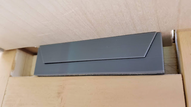
  1. If the gates are always in alignment this will go a long way to ensuring that the rails are also in alignment. I 3D printed two nesting parts, one of which is attached to the underside of the gate (the "male" part) where it inserts into the other part mounted on the vertical upright (the "female" part). A picture is worth a thousand words:


The upper "male" part resting in the lower "female" part.

These 3D printed parts ensure that each gate is guided into position without any lateral movement.

The other feature that ensures that the track aligns with minimal gaps for the join is the design of the hinged ends. Each of these makes use of a tabbed design which ensures that the tracks on the gate drop down when the gates are opened. This allows for a very small gap in the rails at the opening and prevents any sort of binding or "collision" that would occur if the rails hinged upwards.

Upper-level gate closed; I was able to use ordinary hinges here.

Upper-level gate opening; note how the track drops below the adjacent track.


Lower-level gate closed


Lower-level gate opening; again, note how the track is dropping.


For the lower level, I had to use these cabinet hinges because I didn't leave enough room for ordinary hinges.


Continued in Part 3 of 4.