Tool for designing Arduino wiring and sketches

In recent years I have become an avid user of Arduino micro controllers, mainly for use in my model railroad hobby. I have used them to control lighting inside structures (random or timed sequencing of numerous lights), controlling signals using two different methods of train detection, operating servos with inputs coming from either push buttons or RFID tags to detect the presence of certain pieces of rolling stock, among others.

One thing I haven't been very good at is maintaining good documentation of my wiring. I have always made rough drawings but these are often difficult for me to interpret a year or two later. Here is an example:

I recently discovered a much better way of doing this. In a matter of minutes, I was able to create the following drawing (it depicts a different project from the above example):


This was created using Tinkercad by Autodesk. I have been using Tinkercad ever since purchasing my 3D printer. I use it to design 3D objects.

I was recently doing some on-line research in connection with my recent project. I am working on model railroad crossing lights operated using several photoresistors to detect the presence of a train and an Arduino for logic as to when the crossing lights should flash. In particular, I wanted a refresher on the use of "pull-up" and "pull-down" resistors. In one of the YouTube videos I watched it was clear that the presenter was using a very clever piece of software with which to do his demonstrations. I was eventually able to determine that he was using Tinkercad.

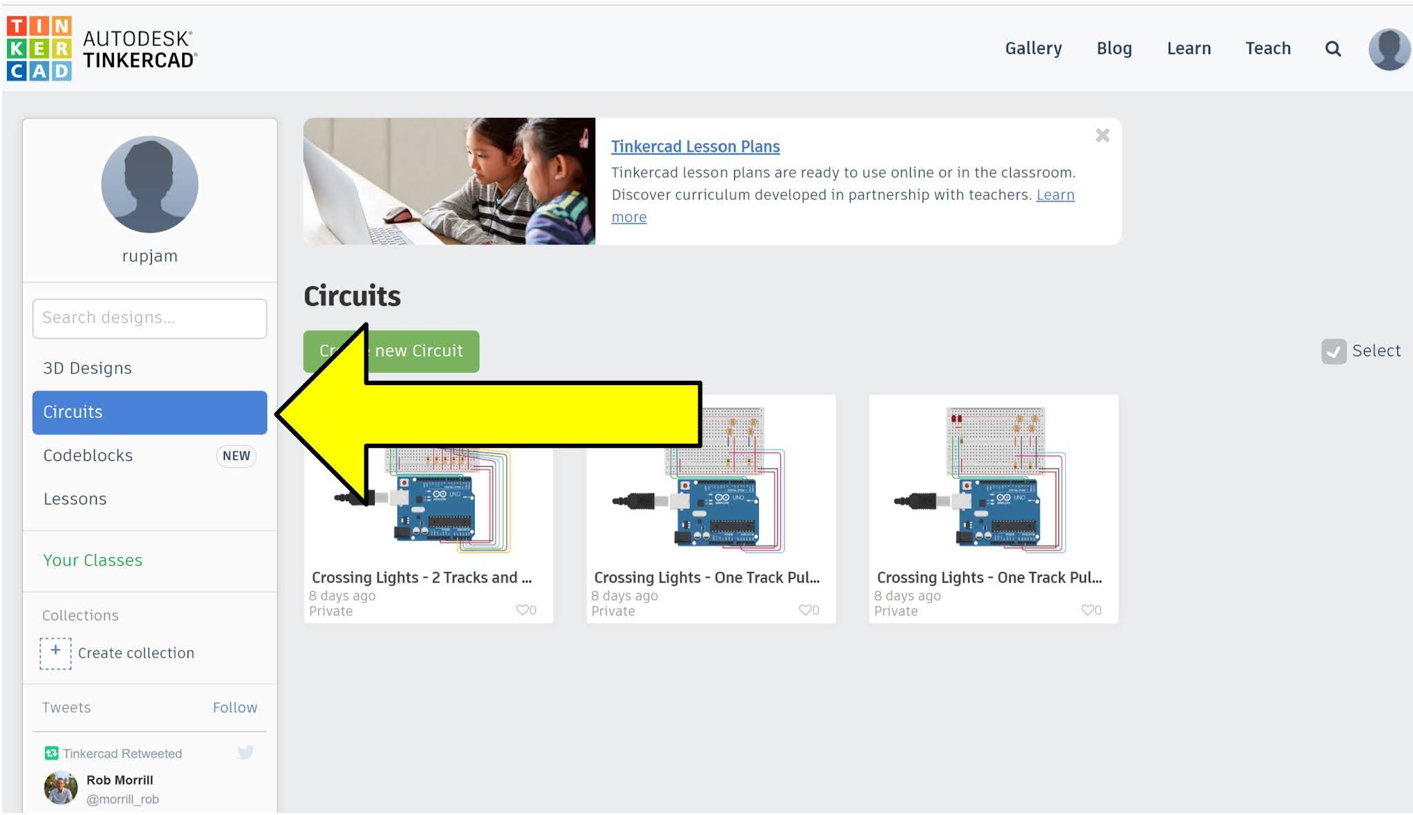
Tinkercad is free - you need to sign in with an email and password (they have never emailed me any unwanted advertising or other junk). Instead of selecting "3D Designs", select "Circuits"as indicated with the arrow below:

Next choose "Create New Circuit" which will take you to this screen where you can select "Arduino" from the pull-down menu on the right where the yellow arrow is pointing:

If you are familiar with Tinkercad you will know that the software will assign it's own random name to every project (the green arrow shows that, in this case, it selected "Sizzling Kup"). By clicking on this name you can assign your own name to the project by typing over the random name.

Clicking the yellow arrow above results in the following pre-made circuits down the right-hand side of the page. At time of writing there are 22 circuits and one that is strictly a breadboard wired to an Arduino that can be used to design your own circuits.

Using the pre-made circuit named "Servo" for illustration, click/drag it into the white workspace, as shown:


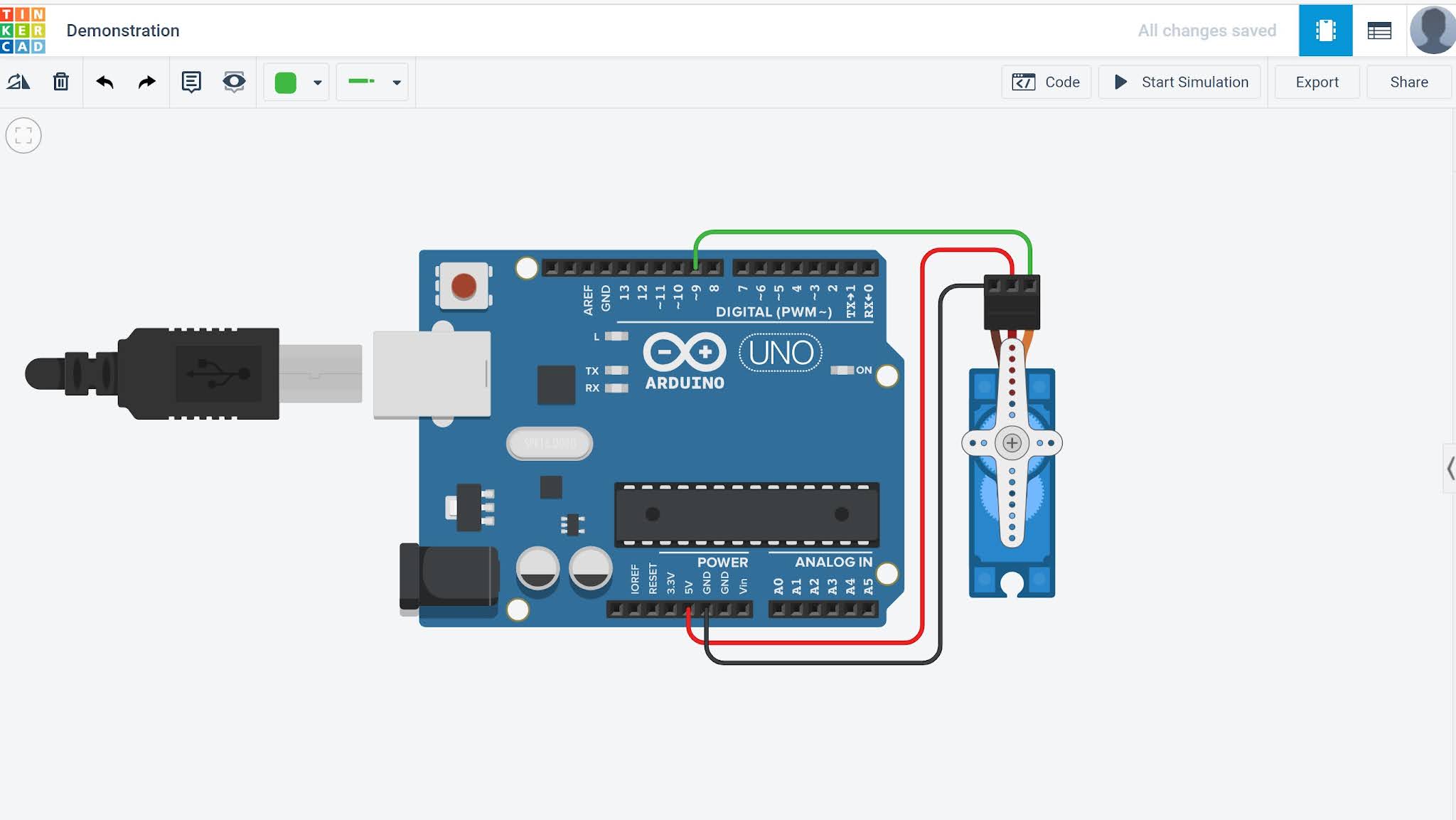
As you can see this is a drawing of an Arduino UNO microcontroller wired to a servo. The wires can be dragged and dropped to other pins, more wires can be added and the shape and colour of the wires can be changed.

In addition to the above, by clicking on the "Start Simulation" box in the top right corner of the screen the graphically depicted USB cable will plug into the Arduino. This powers it up and the servo will move according to how the Arduino is programmed.

Clicking on the "Code" box to the left of the "Start Simulation" box will reveal the following:


These are called "blocks". Those on the left will allow you to simply and graphically create Arduino programming code (C++). Those coloured blue are Outputs, purple are Inputs, etc. Select the desired block on the left and drag it to the screen on the right. Some of these contain variable parameters such as milliseconds or counter values. 

Clicking on the pull-down menu labelled "Blocks" reveals three choices, Blocks, Blocks + Text or Text. Text is the C++ code that can be copied and pasted directly into the Arduino software (Arduino IDE).

Numerous circuit components including resistors, capacitors, LED's, servos, motors, etc. are found in the same pull-down menu on the right where you found the Arduinos. Simply drag and drop the components to where you want them and connect them using the wire colour and type that you wish.

This tool allows you to design a circuit, write the code and test the code all on your computer. Once you are satisfied with what you have built you can use your drawing to create your invention using actual components. The clean graphics will allow you to save a documentation copy for future reference or to share it with others using a blog or by email. With the code copied into the Arduino IDE you can upload it into your actual Arduino to run your circuit.

As for practically everything in life there are YouTube videos available to help get you started. The official Autodesk Tinkercad channel is here: YouTube

Kudos to the creators of this tool who have put a lot of thought into its design.

3D Printed Gear Toys

Our 3-year old grandson has an intense interest in understanding how things work. He shows more interest in household appliances than he does children's toys. My wife and I recently spent a week with our daughter, her husband and our grandson. I thought it might be fun to have a "gear of the day" and present the little guy with a new device every day. I located all of the following on Thingiverse and printed them on my 3D printer. Credit for the creation of these is as follows:

Gear Trio - ThreeHamsWillKillHim

Nautilus Gears - MishaT

Fidget Bolts (I added an extra component to make this more robust) - LarkysPrints

Gear Toy - deltamodulator

Elliptical Gears - cohlwiler

Geneva Wheel - PrintTo3D

Square Gears - zefram

Planetary Gears (I added the removable rods so a child could turn the gears more easily) - engrenage planétaire


HO Vacuum Car

I have a couple of excellent track cleaning cars which I use once or twice a year to remove dirt accumulation from the rails of my model railroad. The use of graphite or NO-OX-ID on the rails allows for such long intervals between cleanings. See my blog posts of September 11, 2020 and August 21, 2021 which outline these methods.

Track cleaning cars only clean the rails. They do nothing to remove the light layer of household dust that falls on the entire layout. Ideally, a vacuum cleaner should be used from time to time. However, this is one of those jobs that is quite prone to procrastination, at least for me.

I am aware of a couple of commercially built HO scale cars that contain small vacuum cleaners. However, I thought I would tackle making my own. Here is a picture of the final result:

This is how I built this car:

  1. I began with a Roundhouse Hobbies high-cube boxcar. As with most such cars, the floor of the car complete with both trucks and couplers is easily detached from the car body. I removed the steel weight that was fastened to the floor of the car with two plastic pins and double-sided tape. The components that will be added to the car will provide sufficient weight to allow the car to track well.

  2. Using my 3D printer I created an oval-shaped insert that will serve as the vacuum nozzle on the underside of the car. The interior is slightly cone-shaped to create a venturi effect to the flow of air sucked in to the car. Here is a graphical depiction of this, showing the nozzle from two perspectives:


  3. I carefully cut a hole in the underside of the car slightly to one side of the mid-point of the car to fit the nozzle.

  4. I next cut the bristles off an inexpensive synthetic paintbrush and carefully glued a thin wall of bristles around the outside perimeter of the nozzle using Gem-Tak adhesive (available from Michaels and Amazon):


    Once the adhesive set I trimmed the bristles so they reached about halfway between the railheads and the tops of the ties using a sharp pair of small scissors. I cut away slightly more bristle material where the bristles rub on the rails. Later, when the car was complete and much heavier because of the various components inside, the bristles can be "fine tuned" to eliminate derailments that arise if they are too long. I had to remove the first set of bristles and apply new ones because I was too aggressive at cutting away the first set of bristles. The purpose of the bristles is to help stir up some of the dust but, more importantly, to help ensure that the vacuum force is as strong as possible at the top of the ties and ballast.

  5. I needed to create the means by which electrical energy could pass from the rails, through the metal wheels (insulated on one end of each axle), through the axle and into the car itself. For this I used the same wiper system I explained in my blog entry of December 21, 2020 titled Flicker-free Car Lighting.

  6. I had two 12 VDC brushless fans in my parts bin that I have owned for years. I don't recall where I obtained these from but they appear to be cooling fans from some sort of electronic device. I likely purchased these from either Princess Auto or B&E Electronics. I carefully cut an opening in the top of the car to accommodate the fans, as follows:


  7. I next installed a small sliding on/off switch through the underside of the car bottom.


  8. I next built the circuit which will power the fans with slightly more than 12 VDC. The circuit consists of a bridge rectifier (minimum 1 amp), five 3-volt 1-farad supercapacitors wired in series and a 5-ohm resistor. Note that the sum of the voltage ratings of the capacitors must be more than the maximum voltage that they will be subjected to [5 X 3 volts = 15 volts; there is more than enough margin between 12 volts and 15 volts; if the sum of the voltages is exceeded the capacitors will "pop" (i.e., in a mini explosion)]. These components are available from DigiKey or Mouser. The resistor is placed in the circuit to slow the in-rush current as the supercapacitors are charged (a high in-rush current can be interpreted as a short circuit by the Digital Command Control ("DCC") system). The circuit diagram is as follows:


  9. I next 3D printed the container shown in the following photo. It is mounted over the top of the vacuum intake nozzle. At one end the container is a space into which a fairly thin piece of filter material can be inserted (this is the roll-type filter material that can be purchased from many hardware stores). The container is mounted onto styrene so the underside of the container fits snugly. A piece of styrene is positioned at one end as a retainer for the container and a styrene swivel is positioned at the other end to hold it firmly in place. When the top of the car is mounted in place the fans blowing out from the car create a negative pressure inside the car. This causes air to flow upward through the intake nozzle and out of the container through the filter material. The filter material traps the dust in the container.

  10. Finally, the male side of a two-conductor connector was mounted to the car floor using hot glue. The female side of the connector was mounted to the inside of the car top. When the car top is lowered into position the connectors mate, completing the circuit to the fans. See the arrow pointing to the connector in the diagram below. This connector is one of many different connectors I have collected over the years; I don't recall the source. However, connectors are easy to come by.


  11. Finally, I used my 3D printer to print a grille to cover the fan outlets as well as to cover the tops of the fans.

Here is a photo of the finished vacuum car.


It gathers a surprising amount of dust. It is not powerful enough to pick up heavier objects such as loose ballast. The fans make a low whine when they are running but it is not bothersome. I simply include the vacuum car in a train occasionally to take care of dust along the rails. If there is any interruption in the power to the car, such as over a turnout, the supercapacitors keep the fans running at top speed. If the car is removed from the rails while operating the fans will run for about 15 seconds before the supercapacitors are fully discharged.