Showing posts with label Arduino. Show all posts

Crossing Signals - Part 4 of 4 - The Arduino Code

If you have not experience with the coding of the programming language for Arduino microcomputers this is not the blog entry where you will learn about it. However, if you have been following along and would like to see the code I developed, please feel free to copy the following Arduino sketch and upload it to your own Arduino. However, as your model railroad will almost certainly have a different track configuration you will need to modify the coding as necessary to suit your particular situation. I would be pleased to help anyone who has a question. You can email me at rupertsinsights@gmail.com.

Here is my code:

/*---------------------------------------------------------------------------
  This Arduino sketch and the circuit diagram in Part 3 of 4 is used to control model railroad crossing
  lights that warn vehicular traffic about the danger of an approaching train. This design does not include
  the use of sound as listening to crossing sounds quickly becomes tiresome. However, sound
  could easily be added with the addition of an Arduino sound shield and a small addition to
  the coding. The particular circumstance on the model railroad for which this was designed
  has the highway crossing two tracks, the main line and a branch line, which means there
  are two level crossings in use. Also, at the east side of the level crossing there
  are four possible tracks from which a train can approach the level crossing (the main
  line from the east, a siding that joins the main line immediately to the east of the crossing,
  the branch line from the east and a spur that joins the branch line immediately to the east
  of the crossing).

  The presence of train cars is detected with the use of light sensitive photoresistors. A photoresistor
  is a device allows electrical current to pass through with very little resistance when it
  is exposed to light. When the light source is removed (by the light being extinguished or the
  photoresistor shaded by the presence of an object such as a model train) the photoresistor's
  resistance increases. The amount of resistance is continuously variable (i.e., is analog and not
  digital). This is the same principal used by many devices in our daily lives (smart phones and smart
  TV's use photoresistors to detect how much light is present in order to vary the brightness of the
  screen, street lights use photoresistors to control when they turn on, etc.). In this instance
  an Arduino microcontroller is used to sense the increased resistance caused by the shading of
  photoresistors which, in turn, causes the Arduino to flash pairs of red LEDs which are mounted
  in the crossing signals facing both sides of the highway.
  
  Photoresistors can be wired in series. If two are wired together in series, shading either one
  or both photoresistors will cause the current passing through them to drop.

  In this design, photoresistors are mounted in the centre of the model railway tracks, between
  the ties and with the tops of the photoresistors flush with tops of the ties. There are six
  photoresistors which have been designed as the "OUT" locations - those locations described in the
  first paragraph above that a train will cover is it approaches the crossing from a distance. In
  addition, photoresistors are mounted immediately adjacent to the level crossing roadway on both
  sides of the roadway, again in the centre of the track with the tops of the photoresistors flush
  with the tops of the ties (the "CROSSING" photoresistors).
  
  The shading of any one of the "OUT" photoresistors tells the Arduino that a train is approaching
  the crossing and the Arduino starts flashing the crossing lights. The shading of any one of the
  "CROSSING" photoresistors tells the Arduino that the train has now reached the crossing so the
  Arduino keeps flashing the crossing lights. Once the last car has passed the last "CROSSING"
  photoresistor the lights stop flashing after a predermined amount of time that can be adjusted
  (it is not desirable for the lights to stop flashing while a train is still across the crossing
  but it equally undesirable if the lights continue flashing long after a train has passed).
  
  This program self-calibrates the photosensors based on the amount of light falling on the
  photosensors at the momment the Arduino is first turned on. This means that all photosensors must
  not be covered when the Arduino is first turned on. Also, it helps if the ambient light in the room
  remains fairly constant during the time that the Arduino is operated. If the ambient light reduces 
  the self-calibration will take this into account but is not able to cope with large increases in 
  ambient light. If there is a large increase in ambient light then it is simply matter of removing
  power from the circuit momentarily and then allowing it to reboot.
  
  It would have been possible to wire all six OUT photoresistors in series. However, as they are
  located several feet away from each other it is very likely that the amount of ambient light falling
  on each one is quite different. This would mean that the self-calibration would likely not be as
  sensitive as one would like. For this reason, photoresistors that are located in close proximity are
  wired in series and the Arduino self-calibrates each pair together. One pair is designated OUTWest, another is
  OUTEast1, a third is OUTEast 2 a fourth is CROSSING1 and the last is CROSSING2.
 
For ProMini or UNO September 24, 2021
  -------------------------------------------------------------------------------*/
//Assign the various sensor pairs to Arduino pins:
const int sensorOUTWest = A0;
const int sensorOUTEast1 = A1;
const int sensorOUTEast2 = A2;
const int sensorCROSSING1 = A3;
const int sensorCROSSING2 = A4;

//Designate a counter for how long sensorOUT is covered
//and a limit after which the lights will stop flashing:
int countOUT = 0;
int countOUTLimit = 8;

//Designate a counter that starts at the value of
//countDownStart which determines how long crossing lights
//flash after a train has passed the level crossing.
//The higher the value of countDownStart, the longer
//the crossing lights will flash after the train has passed.
int countCROSSING = 0;
int countDownStart = 1;

//Counter to allow a train to pass over a second OUT sensor
//after it has passed over the level crossing to avoid
//triggering a new flashing light sequence.
int countFALSE = 0;
                                                       
//Following variables adjust how much time passes for
//the Arduino to reset once a train has passed over
//a second OUT sensor (the higher these values the
//longer it takes to reset)
int countFALSELimit = 15;
int delaySensitivity = 200;

//Following values are assigned based on whether a
//photosensor is shaded enough to trigger a crossing
//light sequence (in effect converts the analog
//photoresistor into a digital device, simply to
//make the program logic simpler.
int coveredOUT = 0;
int coveredCROSSING = 0;
int currentSensorState = 0;
int lastSensorState =0;

//The value of inTransit depends on where a train is
//located in its progression towards, over and beyond
//the level crossing. The value of inTransit is what
//causes the crossing lights to either flash or not.
int inTransit = 0;

//The amount by which the light falling on eash sensor
//must drop to start detection logic.
int lightThreshold = 75;                            

//measures amount of light falling on sensor OUT:
int valOUTWest; 
  
//Starting point of variable valOUT (will increase to
//highest reading of val:                                  
int valOUTWestHigh = 0;

//Starting point of variable valOUT (will decrease to
//lowest reading of val):
int valOUTWestLow = 1023;

//A variable that will be equal to the value of
//valOUTWestHigh MINUS the value of lightThreshold:
int valOUTWestTest;                                 

//The following are all similar variables as the above
//for the various other photoresistor pairs
int valOUTEast1;
int valOUTEast1High = 0;
int valOUTEast1Low = 1023;
int valOUTEast1Test;

int valOUTEast2;
int valOUTEast2High = 0;
int valOUTEast2Low = 1023;
int valOUTEast2Test;

int valCROSSING1;
int valCROSSING1High = 0;
int valCROSSING1Low = 1023;
int valCROSSING1Test;

int valCROSSING2;
int valCROSSING2High = 0;
int valCROSSING2Low = 1023;
int valCROSSING2Test;

int LED1 = 2;
int LED2 = 3;

void setup()
{
  pinMode(sensorOUTWest, INPUT);
  pinMode(sensorOUTEast1, INPUT);
  pinMode(sensorOUTEast2, INPUT);
  pinMode(sensorCROSSING1, INPUT);
  pinMode(sensorCROSSING2, INPUT);
  pinMode(LED1, OUTPUT);
  pinMode(LED2, OUTPUT);
  Serial.begin(9600);
}

void loop()
{
  checkAllOUTSensors();
  checkAllCROSSINGSensors();

//Outer sensor detects train; train has not reached crossing
  if (coveredOUT == 1 && coveredCROSSING == 0 && inTransit == 0)        
  {
//Add to value of counter as long as outer sensor detects train  
    countOUT = countOUT + 1;  
    
//Train is deemed to be in transit between outer and inner sensors
//and inTransit is assigned value of 1                                          
    inTransit = 1;                                                
  }

//Outer sensor continues to detect train; train has not reached
//crossing; train deemed in transit
  if (coveredOUT == 1 && coveredCROSSING == 0 && inTransit == 1)        
  {
//Counter value stops increasing because train is either continuing
//its travel toward crossing or it has stopped on the OUT sensor    
    countOUT = countOUT;                                                 
  }

//Outer sensor no longer detects train; train has not reached
//crossing; trained deemed in transit
  if (coveredOUT == 0 && coveredCROSSING == 0 && inTransit == 1)
  {
//Add to value of counter as long as train is in transit and is not
//detected by outer or crossing sensors    
    countOUT = countOUT + 1;                                            
  }

//Train doesn't reach crossing in time (as for a train that stops
//on a sensor and then reverses direction)
  if (countOUT > countOUTLimit && countCROSSING == 0)                    
  {
    countOUT = 0;
    inTransit = 0;
  }

//Train reaches crossing
  if (coveredCROSSING == 1 && inTransit == 1)                             
  {
//Value of countDownStart is assigned to countCROSSING    
    countCROSSING = countDownStart; 
    
//inTransit is assigned a value of 2                                      
    inTransit = 2; 
     
//countOUT is reset to 0 because countOUT is no longer
//needed for this train passage                                                      
    countOUT = 0;                                                         
  }


  if (coveredCROSSING == 0 && inTransit == 2 && countCROSSING > 0)
  {
    countCROSSING = countCROSSING - 1;
  }


  if (countCROSSING == 0 && inTransit == 2)
  {
    inTransit = 3;
  }

  if(inTransit == 3 && coveredOUT == 1)
  {
    countFALSE = countFALSELimit;
    inTransit = 4;
  }

  if(inTransit == 4 && coveredOUT == 0 && countFALSE > 0)
  {
    countFALSE = countFALSE - 1;
    delay(delaySensitivity);
  }

  if(inTransit == 4 && coveredOUT == 1 && countFALSE > 0)
  {
    countFALSE = countFALSE;
  }

  if(inTransit == 4 && coveredOUT == 0 && countFALSE == 0)
  {
    inTransit = 0;
  }
  
  if (inTransit == 1 || inTransit == 2)
  {
    digitalWrite(LED1, LOW);
    digitalWrite(LED2, HIGH);
    delay(500);
    digitalWrite(LED1, HIGH);
    digitalWrite(LED2, LOW);
    delay(500);
  }

  else if (inTransit == 0 || inTransit == 3 || inTransit == 4)
  {
    digitalWrite(LED1, HIGH);
    digitalWrite(LED2, HIGH);
  }

  {
    //    Serial.print(" valOUTWest= ");
    //    Serial.print(valOUTWest);
    //    Serial.print(" valOUTWestHigh= ");
    //    Serial.print(valOUTWestHigh);
    //    Serial.print(" valOUTWestLow= ");
    //    Serial.print(valOUTWestLow);
    //    Serial.print(" valOUTWestTest= ");
    //    Serial.print(valOUTWestTest);
    //    Serial.print(" valOUTEast1= ");
    //    Serial.print(valOUTEast1);
    //    Serial.print(" valOUTEast1High= ");
    //    Serial.print(valOUTEast1High);
    //    Serial.print(" valOUTEast1Low= ");
    //    Serial.print(valOUTEast1Low);
    //    Serial.print(" valOUTEast1Test= ");
    //    Serial.print(valOUTEast1Test);
    //    Serial.print(" valOUTEast2= ");
    //    Serial.print(valOUTEast2);
    //    Serial.print(" valOUTEast2High= ");
    //    Serial.print(valOUTEast2High);
    //    Serial.print(" valOUTEast2Low= ");
    //    Serial.print(valOUTEast2Low);
    //    Serial.print(" valOUTEast2Test= ");
    //    Serial.print(valOUTEast2Test);
    //    Serial.print(" coveredOUTEast= ");                              
    //    Serial.print(coveredOUTEast);
    //    Serial.print(" valCROSSING1= ");
    //    Serial.print(valCROSSING1);
    //    Serial.print(" valCROSSING1High= ");
    //    Serial.print(valCROSSING1High);
    //    Serial.print(" valCROSSING1Low= ");
    //    Serial.print(valCROSSING1Low);
    //    Serial.print(" valCROSSING1Test= ");
    //    Serial.print(valCROSSING1Test);
    //    Serial.print(" valCROSSING2= ");
    //    Serial.print(valCROSSING2);
    //    Serial.print(" valCROSSING2High= ");
    //    Serial.print(valCROSSING2High);
    //    Serial.print(" valCROSSING2Low= ");
    //    Serial.print(valCROSSING2Low);
    //    Serial.print(" valCROSSING2Test= ");
    //    Serial.print(valCROSSING2Test);
    //    Serial.print(" coveredOUT= ");                            
    //    Serial.print(coveredOUT);
    //    Serial.print(" coveredCROSSING= ");                      
    //    Serial.print(coveredCROSSING);
    //    Serial.print(" countOUT= ");
    //    Serial.print(countOUT );
    //    Serial.print(" countCROSSING= ");
    //    Serial.print(countCROSSING );
    //    Serial.print(" countFALSE= ");
    //    Serial.print(countFALSE );
    //    Serial.print(" inTransit= ");
    //    Serial.print(inTransit );
    //    Serial.println();
    //    delay(100);
  }
}

void checkAllOUTSensors()
{
//Following routine reads valOUT from photosensor, sets valOUTHigh and valOUTLow 
//and subtracts the value of lightThreshold from the High measurement to detect the presence of a train
  valOUTWest = analogRead(sensorOUTWest);            
                                                     
  if (valOUTWest > valOUTWestHigh)
  {
    valOUTWestHigh = valOUTWest;
  }                                                 
  if (valOUTWest < valOUTWestLow)
  {
    valOUTWestLow = valOUTWest;
  }                                                   
  valOUTWestTest = valOUTWestHigh - lightThreshold;


//Following routine reads valOUT from photosensor, sets valOUTHigh and valOUTLow
//and subtracts the value of lightThreshold from the High measurement to detect the presence of a train
  valOUTEast1 = analogRead(sensorOUTEast1);          

  if (valOUTEast1 > valOUTEast1High)
  {
    valOUTEast1High = valOUTEast1;
  }                                                 
  if (valOUTEast1 < valOUTEast1Low)
  {
    valOUTEast1Low = valOUTEast1;
  }                                                   
  valOUTEast1Test = valOUTEast1High - lightThreshold;

  
//Following routine reads valOUT from photosensor, sets valOUTHigh and valOUTLow
//and subtracts the value of lightThreshold from the High measurement to detect the presence of a train
  valOUTEast2 = analogRead(sensorOUTEast2);            
                                                     
  if (valOUTEast2 > valOUTEast2High)
  {
    valOUTEast2High = valOUTEast2;
  }                                                 
  if (valOUTEast2 < valOUTEast2Low)
  {
    valOUTEast2Low = valOUTEast2;
  }                                                   
  valOUTEast2Test = valOUTEast2High - lightThreshold;
                                             

//If valOUT is less than valOUTTest then sensor OUT is not covered
//so sensor is given a value of 1
  if (valOUTWest < valOUTWestTest || valOUTEast1 < valOUTEast1Test || valOUTEast2 < valOUTEast2Test)       
  {
    coveredOUT = 1;                                    
  }
//If valOUT is greater than valOUTTest then sensor OUT is covered
  else if (valOUTWest >= valOUTWestTest || valOUTEast1 >= valOUTEast1Test || valOUTEast2 < valOUTEast2Test)                        
  {
    coveredOUT = 0;
  }

}

void checkAllCROSSINGSensors()
{
//Following routine reads valOUT from photosensor, sets valOUTHigh and valOUTLow
//and subtracts the value of lightThreshold from the High measurement to detect the presence of a train 
  valCROSSING1 = analogRead(sensorCROSSING1);          
  if (valCROSSING1 > valCROSSING1High)
  {
    valCROSSING1High = valCROSSING1;
  }                                                 
  if (valCROSSING1 < valCROSSING1Low)
  {
    valCROSSING1Low = valCROSSING1;
  }                                                   
  valCROSSING1Test = valCROSSING1High - lightThreshold;


//Following routine reads valOUT from photosensor, sets valOUTHigh and valOUTLow
//and subtracts the value of lightThreshold from the High measurement to detect the presence of a train
  valCROSSING2 = analogRead(sensorCROSSING2);          
  if (valCROSSING2 > valCROSSING2High)
  {
    valCROSSING2High = valCROSSING2;
  }                                                 
  if (valCROSSING2 < valCROSSING2Low)
  {
    valCROSSING2Low = valCROSSING2;
  }                                                   
  valCROSSING2Test = valCROSSING2High - lightThreshold;
                                       

//If valCROSSING is less than valCROSSINGTest then sensor CROSSING is not covered
//so sensor is given a value of 1
  if (valCROSSING1 < valCROSSING1Test || valCROSSING2 < valCROSSING2Test)                             
  {
    coveredCROSSING = 1;                                    
  }
//If valCROSSING is greater than valCROSSINGTest then sensor CROSSING is covered 
  else if (valCROSSING1 >= valCROSSING1Test || valCROSSING2 >= valCROSSING2Test)                       
  {
    coveredCROSSING = 0;
  }
}

Crossing Signals - Part 3 of 4 - Designing the Circuit

As alluded to in Part 2 of 4 of this series of posts, I used an Arduino Pro Mini to handle the detection of trains and activation of the flashing crossing lights. On September 21, 2021 I discussed a handy tool for drawing wiring diagrams for Arduino circuits. Following is such a wiring diagram showing the wiring of my crossing light circuit on a breadboard. A breadboard is a device into which various electronic components can be plugged without the need to solder the components. This allows for the inevitable tinkering that is required in the design and testing of a circuit. Once one is satisfied with the circuit, a more permanent circuit can be created by soldering the various components together to create the final circuit.


The above diagram shows an Arduino UNO in the circuit. I used an Arduino Pro Mini in my final circuit because it is much smaller (width is about the size of a quarter-dollar coin) and cheaper but it has the same terminals and processing capacity as the UNO.

Note that the photoresistors are wired in series in pairs labelled 1 through 5. Following is a sketch showing which sensors on my model railroad correspond to those in the wiring diagram:


You will note that each pair of photoresistors are those that are physically closest to one another. While the lighting of my layout is fairly uniform, there are likely subtle differences in lighting that are not easily detectable with the naked eye (or even an eye with its clothes on!). As described in Part 2 of 4 in this series, photoresistors are linear devices that vary their amount of resistance to electrical current depending on how much light does or does not fall on them. I wanted the amount of light falling on each pair of photoresistors to be as consistent as possible because the Arduino detects the presence of rolling stock by comparing the amount of current running through each pair of photoresistors when fully lit against the amount of current when shaded by rolling stock.

Please note that I have not always been consistent with my terminology. My use of the words "sensor" and "photoresistor" mean the same thing.

In Part 4 of 4 of this series I will share the Arduino C++ code used to operate this circuit. I used the above breadboard configuration as I tinkered with the logic to make the crossing lights flash as I wanted them to. Once I was satisfied that the circuit behaved as I wanted it to, I recreated the circuit by soldering components to a PC board that is configured the same way as a breadboard. The following are two photos of the final product taken from two sides.


The green, yellow, orange, red and brown wires are those that go to the photoresistor pairs.

The blue, purple, grey, white and black wires all go from the positive side of the circuit to the photoresistor pairs.

The black and red wires (on the left in the first photo and on the right in the second photo) are from the 12 volt DC accessory buss under my layout. The little silver device is an L7805 voltage regulator which converts the 12 volts DC to the 5 volts DC which the Arduino needs to operate. In the first schematic of this blog post, the graphic shows a USB cord that supplies the 5 volts DC coming from the USB port of a computer. This voltage regulator takes the place of the USB cord. Following is a diagram from the Internet showing how to wire such a voltage regulator:


Crossing Signals - Part 2 of 4 - The Methodology for Train Detection

  The following sketch illustrates my track plan (not to scale):


The vertical brown strip depicts the road that passes over two level crossings. The Main Line (also referred to as Track 1) and the Branch Line (also referred to as Track 2) connect via the turnouts located to the East of the roadway. There are 6 possible directions of travel of rolling stock (see yellow arrows in the sketch below):

  • West to east on Main Line
  • West to east on Branch Line
  • East to west on Main Line
  • East to west from Main Line Siding and then on Main Line
  • East to west on Branch Line
  • East to west from Branch Line Spur and then on Branch Line


As my track already has electronic occupancy detection to control the signals (see blog post of December 1, 2020) I decided to use photoresistors to detect the presence of rolling stock. Photoresistors are inexpensive little electronic devices that, when exposed to light, create very little resistance to current flow. However, when the light is turned off (or shaded, as when model railroad passes over it) the level of resistance goes up. Photoresistors are non-polar in that they do not need to be hooked up to positive and negative leads in any particular way. They are analog and not digital meaning that the level of resistance varies depending upon how much light shines or does not shine, on them. Finally, as with regular resistors, photoresistors can be wired in series which means that if two are wired in series, shading one will increase the resistance of the whole circuit and shading both will also increase the resistance of the whole circuit. This is what the photoresistors look like (the head is roughly 4 to 5 mm across, depending on the direction measured - note that two sides are flat):


In order to detect rolling stock travelling from each of the six directions above I mounted photoresistors between the rails, flush to the ties, (called OUT sensors) at the locations marked in green below (sensors are not to scale). The photosensors, along with the crossing lights, will be wired to an Arduino Pro Mini microcontroller. The Arduino programming will be described in detail in Part 4 of 4.


Next, I mounted photoresistors between the rails adjacent to each crossing (called "CROSSING" sensors), as depicted by the blue dots below:


Let's follow a train travelling from West to East along the Main Line.


Position 1 (note the red arrow with the red "1" beside it) - the train shades the first OUT sensor. The Arduino will detect the presence of the train and start the crossing lights flashing. At this point the train could do one of three things:
  1. The train stops at position 1, shading the photoresistor. This means that the crossing lights will keep flashing for as long as the train is parked. This is prototypical. On many occasions I have stopped my vehicle at a level crossing at which the lights are flashing red and look down the track to see that the train is not moving. In this circumstance it is allowable to drive across the level crossing as long as you have come to a complete stop and have checked to make sure that the train is stopped and that it is safe to pass (much light a flashing red traffic light). However, it is not permitted to pass if physical crossing arms are in use at the crossing and the arms are in the lowered position.
  2. The train stops at position 1 and then reverses direction. The crossing lights must stop flashing because there is no longer a need for traffic to be stopped.
  3. The train does not stop but continues on its eastward journey. In this case the crossing lights must keep flashing.
Position 2 - the train has continued its journey and has now reached the level crossing. In this case the crossing lights must keep flashing for the entire time that the train occupies the level crossing.


Position 3 - the train passes over the second CROSSING sensor and, when the last car has passed, the lights must stop flashing.


Position 4 - the train passes over another OUT sensor. As the train has already passed over the level crossing it is important that the crossing lights DO NOT start flashing again. The Arduino needs to be able to differentiate between a train crossing an OUT sensor for the first time and another OUT sensor for a second time. However, once the last car of the train has passed over the second OUT sensor if it were to stop and then reverse direction to pass over the level crossing in reverse the Arduino must start the crossing lights flashing again.


The sequence must operate in exactly the same way no matter the direction of travel or the path followed.

Note that my crossing light design does not incorporate the bell sound. I have seen model railroads with this feature and is nice at first. However, after a while the novelty wears off and ringing bell becomes annoying, at least it does to me. It's my model railroad so I get to decide whether or not the crossings have bells! It would be a simple matter to attach a sound shield to the Arduino and, with some minor programming tweaks, incorporate the bell ringing effect.

In Part 3 of 4,  I'll explain how I wired this contraption.

Crossing Signals - Part 1 of 4 - Building the Crossing Lights

I have long wanted to have operating signals on my model railroad. These are the signals that flash to tell motorists of an approaching train. These are commercially available but I enjoy the problem-solving challenge of scratch building something myself so I thought I would take this on as a new project. This is the first of four blog entries on this topic which will include:

Part 1 of 4 - Building the Crossing Lights

Part 2 of 4 - The Methodology for Train Detection

Part 3 of 4 - Designing the Circuit

Part 4 of 4 - The Code

I first needed to determine the dimensions of crossing signals. A quick online search of "Canadian Grade Crossing Standards" located the following Transport Canada site which contains graphical images and dimensions along with far more information than I will ever need: Transport Canada Grade Crossing Standards. At the bottom of the page is a link to a 60-page PDF file that also contains all the information.

For those readers familiar with the US-style sign which has the words "Railroad" and "Crossing" on the crossbucks, this style has not been in use in Canada for decades. Being an officially english/french bilingual country, Canada removed all words from its crossing lights. This is a graphic taken from the above-mentioned guide:


While the above guide was helpful I wanted to see some real-world pictures of some signs because, depending on when the sign was constructed, the physical appearance of the sign components vary. Using Google Maps to look up crossings within a few kilometres of where I live I quickly was able to take screen shots of a few samples. Here is one:


Using a punch I cut sixteen 7.4 mm disks out of 0.01" thick styrene and in the centre of eight of these I cut a 3 mm hole. The other eight were cut to remove about 1/3 of the area. The following picture shows the first cut on the left. One of these is then turned into the piece in the centre (which houses the light) and the other is turned into the piece on the right (which shades the light).


I wrapped the shade piece on the right around a steel rod that was approximately 4 mm in diameter and held it place for a couple of hours with a clamp to create a slight bend. I then placed it on the light housing, applied a small amount of liquid styrene cement and coaxed the shade into position, holding it a few seconds as the cement dried.

Next, I built the lights that slide into the above housing. The following shows two red 3 mm LEDs. When working with LEDs it is extremely important to keep in mind that, unlike incandescent light bulbs, LEDs are polarity dependent. They will only work if the anode (the longer leg) is powered from the positive side of a power supply and the cathode (the shorter leg) is connected to the ground or the negative wide of the same power supply.


I decided I would use a 3/32" outside diameter hollow brass rod for the pole. In this way the pole itself can be used as a conductor of electricity. Each leg of the two LEDs will be soldered together and, in turn, ONE of them soldered to the outside of the hollow brass rod. In this way the brass rod acts as a conductor and only two thin wires need to be passed up through the hollow brass rod and connected to the other joined legs. I decided that I would wire my LEDs with common anodes (the long, positive legs of the LEDs). However, as I needed to cut both legs of each LED to be much shorter I put a small black dot on the side of the anode (positive) side of the LED at this stage so I didn't get confused over which was which when the legs are shortened.

I pressed one of the cutoff LEDs onto a wooden toothpick, as shown (note the black mark denoting anode):


I then added a second LED from the other side and soldered both legs together.


Using one of the legs that I had earlier cut off I soldered the common anodes together, as follows:


I then repeated the process to create the lights for the other crossing light:

Using a small file I cut a small opening in the wall of the hollow brass rod which is where one thin wire will pass through to the cathode (negative leg) of one of the pairs of LEDs and another thin wire will pass through and be soldered to the cathode of the other pair of LEDs. I then soldered the wire connecting the common anodes to the outside of the hollow brass rod, on the side OPPOSITE the location of the hole, as follows:


This photo shows the wires soldered in place. The red wire is soldered to the bottom of the brass rod. The blue and black wires are both fed through the tube and out of the hole. The blue wire is soldered to the cathodes of one pair of LEDs and the black wire to the cathodes of the other pair of LEDs.


Using the techniques described in my blog post of April 21, 2021 I created the crossbucks and "2 tracks" signs. I then glued the styrene light units onto each LED after painting them black and the signs to the post. I fashioned an electronic bell out of hollow styrene rod and glued it to the top of the pole. Finally, I painted the pole metallic silver.

This is a picture of the finished crossing lights:


Tool for designing Arduino wiring and sketches

In recent years I have become an avid user of Arduino micro controllers, mainly for use in my model railroad hobby. I have used them to control lighting inside structures (random or timed sequencing of numerous lights), controlling signals using two different methods of train detection, operating servos with inputs coming from either push buttons or RFID tags to detect the presence of certain pieces of rolling stock, among others.

One thing I haven't been very good at is maintaining good documentation of my wiring. I have always made rough drawings but these are often difficult for me to interpret a year or two later. Here is an example:

I recently discovered a much better way of doing this. In a matter of minutes, I was able to create the following drawing (it depicts a different project from the above example):


This was created using Tinkercad by Autodesk. I have been using Tinkercad ever since purchasing my 3D printer. I use it to design 3D objects.

I was recently doing some on-line research in connection with my recent project. I am working on model railroad crossing lights operated using several photoresistors to detect the presence of a train and an Arduino for logic as to when the crossing lights should flash. In particular, I wanted a refresher on the use of "pull-up" and "pull-down" resistors. In one of the YouTube videos I watched it was clear that the presenter was using a very clever piece of software with which to do his demonstrations. I was eventually able to determine that he was using Tinkercad.

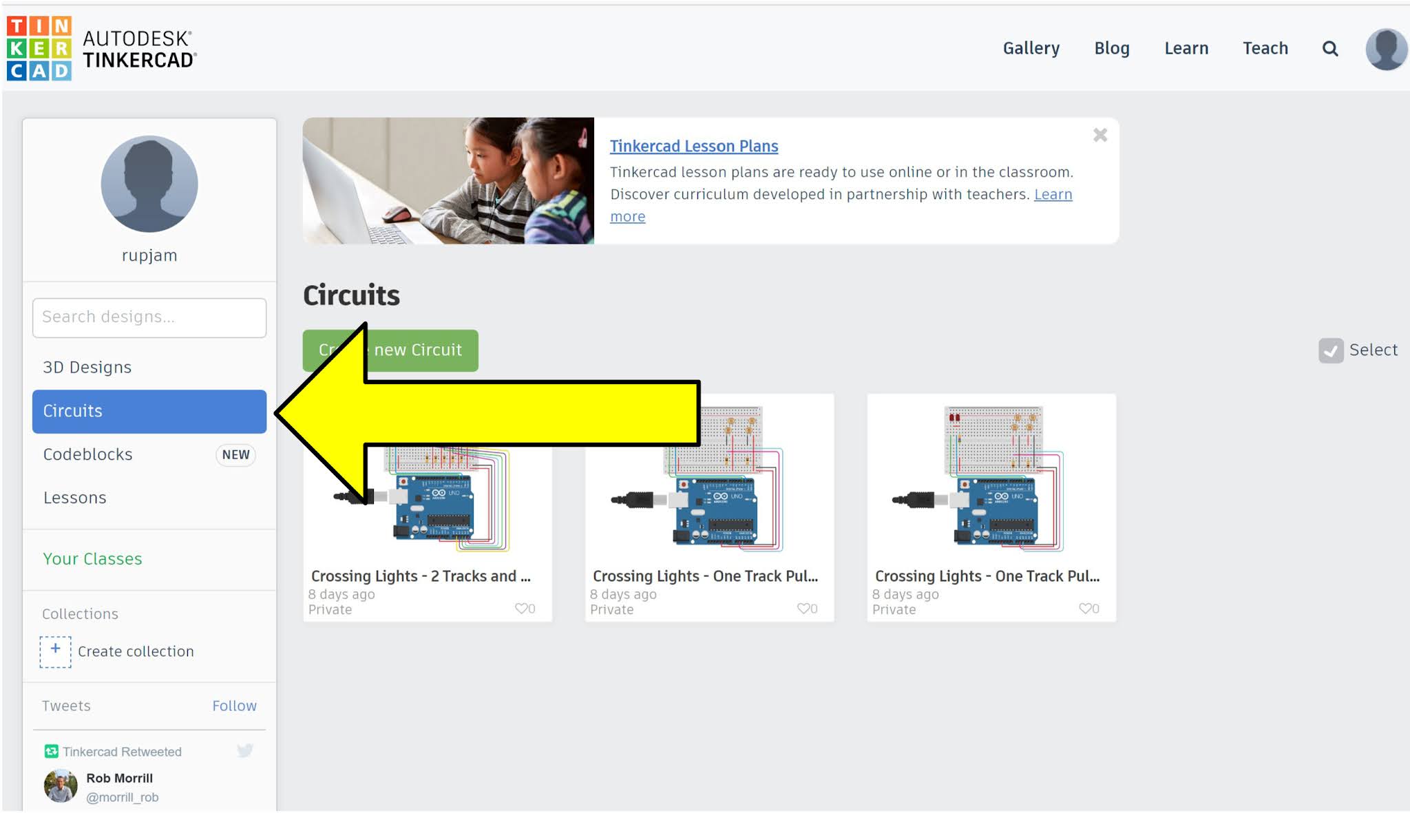
Tinkercad is free - you need to sign in with an email and password (they have never emailed me any unwanted advertising or other junk). Instead of selecting "3D Designs", select "Circuits"as indicated with the arrow below:

Next choose "Create New Circuit" which will take you to this screen where you can select "Arduino" from the pull-down menu on the right where the yellow arrow is pointing:

If you are familiar with Tinkercad you will know that the software will assign it's own random name to every project (the green arrow shows that, in this case, it selected "Sizzling Kup"). By clicking on this name you can assign your own name to the project by typing over the random name.

Clicking the yellow arrow above results in the following pre-made circuits down the right-hand side of the page. At time of writing there are 22 circuits and one that is strictly a breadboard wired to an Arduino that can be used to design your own circuits.

Using the pre-made circuit named "Servo" for illustration, click/drag it into the white workspace, as shown:


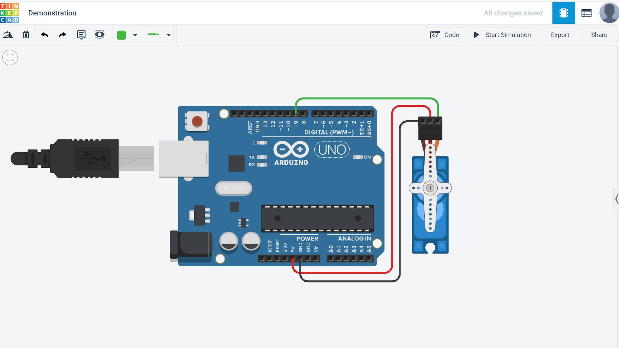
As you can see this is a drawing of an Arduino UNO microcontroller wired to a servo. The wires can be dragged and dropped to other pins, more wires can be added and the shape and colour of the wires can be changed.

In addition to the above, by clicking on the "Start Simulation" box in the top right corner of the screen the graphically depicted USB cable will plug into the Arduino. This powers it up and the servo will move according to how the Arduino is programmed.

Clicking on the "Code" box to the left of the "Start Simulation" box will reveal the following:


These are called "blocks". Those on the left will allow you to simply and graphically create Arduino programming code (C++). Those coloured blue are Outputs, purple are Inputs, etc. Select the desired block on the left and drag it to the screen on the right. Some of these contain variable parameters such as milliseconds or counter values. 

Clicking on the pull-down menu labelled "Blocks" reveals three choices, Blocks, Blocks + Text or Text. Text is the C++ code that can be copied and pasted directly into the Arduino software (Arduino IDE).

Numerous circuit components including resistors, capacitors, LED's, servos, motors, etc. are found in the same pull-down menu on the right where you found the Arduinos. Simply drag and drop the components to where you want them and connect them using the wire colour and type that you wish.

This tool allows you to design a circuit, write the code and test the code all on your computer. Once you are satisfied with what you have built you can use your drawing to create your invention using actual components. The clean graphics will allow you to save a documentation copy for future reference or to share it with others using a blog or by email. With the code copied into the Arduino IDE you can upload it into your actual Arduino to run your circuit.

As for practically everything in life there are YouTube videos available to help get you started. The official Autodesk Tinkercad channel is here: YouTube

Kudos to the creators of this tool who have put a lot of thought into its design.

Automated Signals for Free-mo (Infrared Detection) - Part 3 of 3

Here is the wiring to take the signals from the infrared sensors under each track and also to power the dual signal heads:


I am pleased to report that the system works as designed. Here is a shot of the signal masts:


These masts are mounted on one of the Free-mo modules in my basement layout. I have yet to build any individual dedicated Signal-mos. Once I have done so I shall post pictures.

Automated Signals for Free-mo (Infrared Detection) - Part 2 of 3

 Other components of my signalling system include:

Signal Masts

As with my last signal project described in December, I again made my own signal masts using the same jig described at that time. However, as can be seen in the above picture each mast is double-headed to accommodate signalling in both directions (in my earlier project I used two separate single-headed masts to control traffic in each direction). Since this project is signalling for double-track Free-mo mainline I need signals for both directions for each track so double-headed signals made for less complexity.

Unlike my earlier signalling project for which the signal masts are permanently mounted on the layout, for the Free-mo signals, I wanted a method of making the signal masts removable so they can be stored and transported separately from the Signal-mo modules to lessen the chance of damage.

In the above picture, the grey-coloured base was 3D printed with snug-fitting mounts on which the signal towers fit. The box with the green, yellow and red stripes fits over the signal masts and is fastened shut with Velcro.

Signal Mast Mounts


The grey component is 3D printed to accept a 10-pin female receptacle.


The above picture shows the receptacle mounted in a module. It is fastened with screws from the underside. The bottom of each signal mast has a 3D printed base in which is mounted a male 10-pin connector which plugs into this female base.


Here is a signal mast mounted on the base.

The 10-pin connectors at the bottom of each signal mast are wired as follows:


The red, yellow and green connectors on the left are wired to the three corresponding colour LEDs facing one direction. The other red, yellow and green connectors are wired to the LEDs facing the other direction. The two white connectors are wired to the shaft of the signal mast which is made of brass. The anodes of all the LEDs are wired to the mast. It is important to note that different colours of LEDs draw different amounts of current. Therefore, in order to ensure a comparable brightness of all LEDs I did a bit of experimentation and wired different strength resistors in the wires to each of the different colour LEDs.

The wiring configuration described above means that it doesn't matter which way around a signal mast is mounted - the same contacts will light the same LED colours regardless of which way around the signal mast is mounted.

IR Detector Mounting

My last blog post described the infrared detectors that are to be mounted between the rails. These need to be mounted in place.


The two receptacles for the signal masts are made to fit in a 3/4 inch hole. The holes between the rails for the IR sensors were made using the high-speed hole saw pictured above.


I 3D printed the above fixture which is used to hold the IR sensors in place from beneath the module.


The picture above shows the two signal tower receptacles mounted under the module on the extreme left and the right of the picture and the two IR sensors mounted in the middle. The wires at the bottom of the picture have nothing to do with this project.


I put a thin layer of Flex Paste around the IR emitter and sensor. Flex Paste is one of the "Flex Family of Products" advertised by that very annoying man on TV. What I like about it for this application is, by soaking a Q-tip in isopropyl alcohol one can easily remove excess material and smooth the leftover surface.


This shows all components mounted in the module. I still need to add some ballast to cover the white Flex Paste. When this picture was taken the IR emitter was powered up - you can tell because a digital camera is sensitive to infrared light (tip - if you want to see the infrared signals coming from any such emitter, such as a TV remote control, simply turn on the camera in your smartphone and point it at the output window of the remote and active the remote control button - very handy if you aren't sure whether the remote isn't working only because of a dead battery or because you dropped and broke it!).