Showing posts with label 3D Printing. Show all posts

Animation - Part 2 - Design

I decided to take on the challenge of creating my own track system to create animation. You will note that this uses the concepts used by the Magnorail system referred to in Part 1 but is not an attempt to replicate the Magnorail system. As I don't have access to any Magnorail parts I designed my own parts, several of which appear to be quite different. I also don't know the dimensions of any of the Magnorail parts so I came up with my own dimensions.

I ordered a high-torque 12 volt DC motor from Amazon. The output shaft turns at 5 RPM. I then designed and 3D printed a drive mechanism to sit on top of the motor. Here are pictures of the drive mechanism:

motor mounted to underside of drive mechanism

top side view

with drive gears mounted (note hole the closest gear fits over the "D" gear shaft so it doesn't slip)

same as above but with retainers pressed into holes

Next I created 3D printed chain components which connect to each other and which have holes to fit round rare-earth magnets in a couple of places to move boats:


The track components look like this - each track piece is screwed to a sub-floor which which will reside underneath the styrene sheet "pond":


Here is a picture of the completed track, with the drive mechanism in place:


Here is a picture of the subfloor mounted underneath the pond cutout in the Free-mo module:

The subfloor is mounted with wingnuts to make it easy to remove the subfloor with the track in case adjustments or repairs are ever needed in the future. The motor is wired to a bridge rectifier which takes DCC current from the accessory buss running under the Free-mo module.

Here is a top-side view of the styrene sheet. The beaver dam will be built to disguise the front edge:


Here is a short video showing the boat moving (the rough brown circle painted on the surface is where the beaver lodge will be built):


I will not be sharing the design details or the STL 3D printer files, either for no cost or for a price

Next up......doing the scenery.

Animation - Part 1 - Concept

I am fascinated with animation on a model railroad, whether it be building interior lighting that occasionally turns on and off or motion. Done well, animation brings the model railroad to life and enhances the animation already provided by the movement of rolling stock.

I have a complete Free-mo module built but the scenery has not been completed, aside from the track being ballasted. My vision for this two-part module is as follows:

  • there will be a pond which is cutaway at one edge of the module;
  • the pond was created by a beaver family that dammed a small stream that flows from a culvert under the railway tracks;
  • the beaver dam will be depicted near the edge of the module and a beaver lodge will be somewhere in the centre of the pond;
  • there will be a stately residence beside the pond and a dock where the residents can dock their boat;
  • the boat will sail around the pond without the use of any sort of visible track.

This shows what I have in mind (because of the perspective from which the photo was taken the distance that the boat travels appears much shorter than it will actually be):


I am aware of a commercial product that I could use for this animation.  It is made by Magnorail. They use a plastic chain system that sits beneath a road or lake surface. Magnets can be placed in the chain which cause objects, also with magnets, to travel along the surface. These could include vehicles, boats or one of my favourites, bicycles:


There appears to be only one retailer in North America that handles this product, Reynaulds Euro Imports in Illinois. Their price for a starter set is US$219.95. Once I pay for shipping in US dollars, convert these costs to Canadian dollars and add the import broker fee and Canadian taxes the total cost for the starter kit will come in at around C$400.00 plus. I cannot justify this price, to myself or my wife!

There must be another way...... (to be continued)

3D Printed Gear Toys

Our 3-year old grandson has an intense interest in understanding how things work. He shows more interest in household appliances than he does children's toys. My wife and I recently spent a week with our daughter, her husband and our grandson. I thought it might be fun to have a "gear of the day" and present the little guy with a new device every day. I located all of the following on Thingiverse and printed them on my 3D printer. Credit for the creation of these is as follows:

Gear Trio - ThreeHamsWillKillHim

Nautilus Gears - MishaT

Fidget Bolts (I added an extra component to make this more robust) - LarkysPrints

Gear Toy - deltamodulator

Elliptical Gears - cohlwiler

Geneva Wheel - PrintTo3D

Square Gears - zefram

Planetary Gears (I added the removable rods so a child could turn the gears more easily) - engrenage planétaire


Automated Signals for Free-mo (Infrared Detection) - Part 3 of 3

Here is the wiring to take the signals from the infrared sensors under each track and also to power the dual signal heads:


I am pleased to report that the system works as designed. Here is a shot of the signal masts:


These masts are mounted on one of the Free-mo modules in my basement layout. I have yet to build any individual dedicated Signal-mos. Once I have done so I shall post pictures.

Automated Signals for Free-mo (Infrared Detection) - Part 2 of 3

 Other components of my signalling system include:

Signal Masts

As with my last signal project described in December, I again made my own signal masts using the same jig described at that time. However, as can be seen in the above picture each mast is double-headed to accommodate signalling in both directions (in my earlier project I used two separate single-headed masts to control traffic in each direction). Since this project is signalling for double-track Free-mo mainline I need signals for both directions for each track so double-headed signals made for less complexity.

Unlike my earlier signalling project for which the signal masts are permanently mounted on the layout, for the Free-mo signals, I wanted a method of making the signal masts removable so they can be stored and transported separately from the Signal-mo modules to lessen the chance of damage.

In the above picture, the grey-coloured base was 3D printed with snug-fitting mounts on which the signal towers fit. The box with the green, yellow and red stripes fits over the signal masts and is fastened shut with Velcro.

Signal Mast Mounts


The grey component is 3D printed to accept a 10-pin female receptacle.


The above picture shows the receptacle mounted in a module. It is fastened with screws from the underside. The bottom of each signal mast has a 3D printed base in which is mounted a male 10-pin connector which plugs into this female base.


Here is a signal mast mounted on the base.

The 10-pin connectors at the bottom of each signal mast are wired as follows:


The red, yellow and green connectors on the left are wired to the three corresponding colour LEDs facing one direction. The other red, yellow and green connectors are wired to the LEDs facing the other direction. The two white connectors are wired to the shaft of the signal mast which is made of brass. The anodes of all the LEDs are wired to the mast. It is important to note that different colours of LEDs draw different amounts of current. Therefore, in order to ensure a comparable brightness of all LEDs I did a bit of experimentation and wired different strength resistors in the wires to each of the different colour LEDs.

The wiring configuration described above means that it doesn't matter which way around a signal mast is mounted - the same contacts will light the same LED colours regardless of which way around the signal mast is mounted.

IR Detector Mounting

My last blog post described the infrared detectors that are to be mounted between the rails. These need to be mounted in place.


The two receptacles for the signal masts are made to fit in a 3/4 inch hole. The holes between the rails for the IR sensors were made using the high-speed hole saw pictured above.


I 3D printed the above fixture which is used to hold the IR sensors in place from beneath the module.


The picture above shows the two signal tower receptacles mounted under the module on the extreme left and the right of the picture and the two IR sensors mounted in the middle. The wires at the bottom of the picture have nothing to do with this project.


I put a thin layer of Flex Paste around the IR emitter and sensor. Flex Paste is one of the "Flex Family of Products" advertised by that very annoying man on TV. What I like about it for this application is, by soaking a Q-tip in isopropyl alcohol one can easily remove excess material and smooth the leftover surface.


This shows all components mounted in the module. I still need to add some ballast to cover the white Flex Paste. When this picture was taken the IR emitter was powered up - you can tell because a digital camera is sensitive to infrared light (tip - if you want to see the infrared signals coming from any such emitter, such as a TV remote control, simply turn on the camera in your smartphone and point it at the output window of the remote and active the remote control button - very handy if you aren't sure whether the remote isn't working only because of a dead battery or because you dropped and broke it!).

Automated Signals for Free-mo (Infrared Detection) - Part 1 of 3

Happy New Year! I don't think I have ever felt so good about the start of a new year as I feel now.

In December I posted a two-part article that described the design and construction of my automated signalling system which used block detection to identify the presence of a train. The system continues to work flawlessly.

In earlier posts, I have mentioned my participation in Free-mo (see January 27, 2019 post which explains Free-mo model railroading and March 21, 2020 post which explains that the middle level of my home layout consists of Free-mo modules). I have seen working signalling systems on a Free-mo set up at the Big Valley Alberta event which is hosted by the Calgary Free-mo group and where I found that the added realism makes for a good experience.

I decided that it would be impractical to employ block detection to signalling for Free-mo for the following reasons:

  • Free-mo modules are designed and constructed by various people. Modules can be short (say 2 metres) or long (say 30 metres, in multiple sections). In my experience, most are 2 to 4 metres in length. While the Free-mo standard must be followed for the main buss wiring, this does not mean that the wiring to a module has been designed in such a way that a detection circuit could be installed easily without redoing a lot of the wiring. If a person is reluctant to redo their wiring then the signalling system would be frustrated by one module being "dark".
  • Even if a local group of Free-mo modellers agreed to make the necessary modifications to all of their modules to accommodate block detection, one of the benefits of Free-mo is for people with Free-mo modules from other locations to be able to join the group. Since their modules would not have been modified, their modules would be "dark" for signalling purposes.
  • The design of my block detection signalling system placed signal masts at each end of a block. Say if one were to go to the trouble of rewiring all Free-mo modules for a local group there would need to be added a huge number of wires under each module (with an equal number of reliable connections between module sections) to mount signal masts at the end of each module. The wiring of Free-mo is extensive enough without adding many more wires to the mix. This point only refers to the wiring under each module - also, there would need to be wiring to allow the system to communicate the presence of trains to each adjacent module which adds even more wiring.
I decided that the more practical approach would be to make use of dedicated signal modules "signal-mos" on which the signal masts would be mounted. Each signal-mo would be one foot long and would conform with the "mini-mo" supplemental standard published by Free-mo.org. A mini-mo can be narrower than the normal Free-mo standard but I decided that a layout would look better if the signal-mo is the same width as the adjacent modules. Since the signal-mos would be used on mainline track this means a 26-inch signal-mo width and double track.

All wiring related to the signals would be mounted underneath the signal-mo. The only wiring leading from a signal-mo would be a 6-conductor flat "telephone-style" cable connecting the signal-mo with each adjacent signal-mo. Aside from the normal buss wiring for all Free-mo modules, there would be no other connections to adjacent modules.

The presence of trains would be detected with the use of an infrared detection device which looks like this one which I purchased from eBay:


In this photograph, the device is sitting atop the smallest-size Post-in-Note pad to show scale. One of these would be mounted underneath the centre of each track on each signal-mo. The trim-pot which has an X-shape is used to adjust the sensitivity of the infrared detection. One of the "LED" devices on the left is an infrared light emitter and the other is an infrared light detector. When a train passes over the sensor some of the infrared light bounces off the underside and is detected. The three electrical leads consist of positive and negative leads (5 volts DC) and VCC to which is attached a wire leading to an Arduino mounted underneath the track. One Arduino is required for each of the two tracks. The ground wire is also common with the Arduino.

How the Signals will Operate

The following depicts how the system works without showing any of the electronics or wiring:


Some key points:
  • Two-track mainline; the trains are travelling in the same direction that seems to be conventional "normal" travel when there is a double-track mainline (perhaps those in the UK, Australia, Japan, etc. follow a different practice because they drive their cars on the other side of the road from those of us in North America, Europe, etc.).
  • The rails coloured white for each signal-mo (each of these would be 1 foot long and 26 inches wide). The rails coloured grey depict all other Free-mo modules (anywhere from 1 foot to infinity in length and 26 inches wide at module ends).
  • When the train on the lower track passed over the last signal-mo, the IR sensor mounted under the track triggered the backward-facing signal to show red, protecting the train travelling in the module to the right. This same signal-mo tells the adjacent signal-mo to the left of the occupancy so that signal turns yellow as a warning to approaching trains and the requirement to slow down.
  • The engineer of the train on the lower track sees a green signal because both the next module to the right and the one after that are unoccupied.
  • The same principles apply to the other track and also work the same way if the trains were to be operated in the opposite direction.
What a Signal-mo consists of:


Wiring

The following diagram depicts the wiring mounted underneath each signal-mo:


To wire this under each person's individual module along with all of the other wiring and hardware that is under there would quickly become a nightmare.

The following diagram shows the signal-mo with the 6-conductor flat telephone style wires that take signals to adjacent signal-mos:


Complete Picture

Finally, here is a diagram of the complete picture with only one of the signal-mos showing its wiring:


Coming up - my next post will explain the construction and assembly of the various "real-life" components.


Flicker-free Car Lighting

I am posting this on my favourite day of the year - Winter Solstice. Being the shortest day of the year, each day for the next 6 months gets progressively longer, an optimistic thought when one is in the dead of winter.

I own a set of vintage passenger cars that are well suited to a tourist excursion railway. On September 1, 2020, I posted final pictures of the Free-mo module I built this summer which depicts a tourist excursion railway so one of my next goals was to get my passenger cars ready for showtime.

Here are pictures of one of these cars:


As you can see, the interior is devoid of seats, passengers or lighting. It seems to me that whenever a passenger car is displayed on a model railroad, the absence of seats screams "incomplete". If there are seats, there should be at least a few passengers. The same principle applies to locomotives - many trains on model railroads are devoid of crew in the cab, which seems not only implausible but downright dangerous when the locomotive heads up a running train - but I digress.

Seating is easily accomplished by 3D printing a set of seats to fit the interior. HO scale people can easily be purchased. My challenge was lighting. I wanted to have flicker-free lighting powered by power from the rails. I had seen articles about how to build such a circuit, most recently on Larry Puckett's YouTube channel, The DCC Guy. I based my circuit on Larry's design with one exception. The articles always seem to include a diode in the circuit. However, it seemed to me that I could accomplish the same objective with the judicious selection of appropriately rated resistors.

The components include, per car:
  1. from eBay: phosphor bronze sheet, 0.1 mm thick (for contacts under the car)
  2. from a hobby shop: fine piano wire (also for contacts under the car)
  3. from my parts supply: #2-56 screws to pass from the underside of trucks into car body (to carry current to car interior)
  4. from Mouser: part number 625-DF01M-E3 bridge rectifier (to convert the AC power coming from the track to DC power)
  5. from eBay: LM2596 Mini 360 DC-DC buck converter step down module 4.75v - 23v to 1 v to 17v (to step down the DC voltage coming from the bridge rectifier to 2.9 volts)
  6. from Mouser: part number 581-SCCR12E105SRB 3 volt, 1-farad supercapacitor (to store the 2.9 volts of power coming from the buck converter and feed this voltage to the LED lighting in the car when track power is interrupted)
  7. from Digikey: part number CF14JT51R0TR-ND 51 ohm resistor (to protect the LEDs from over-voltage and also to adjust their brightness) [must be higher resistance than the following resistor]
  8. from Digikey: part number S10HTR-ND 10-ohm resistor (to prevent an inrush of current as the capacitor is charged when track power is turned on which, in turn, can cause a DCC system to interpret this as a short circuit)
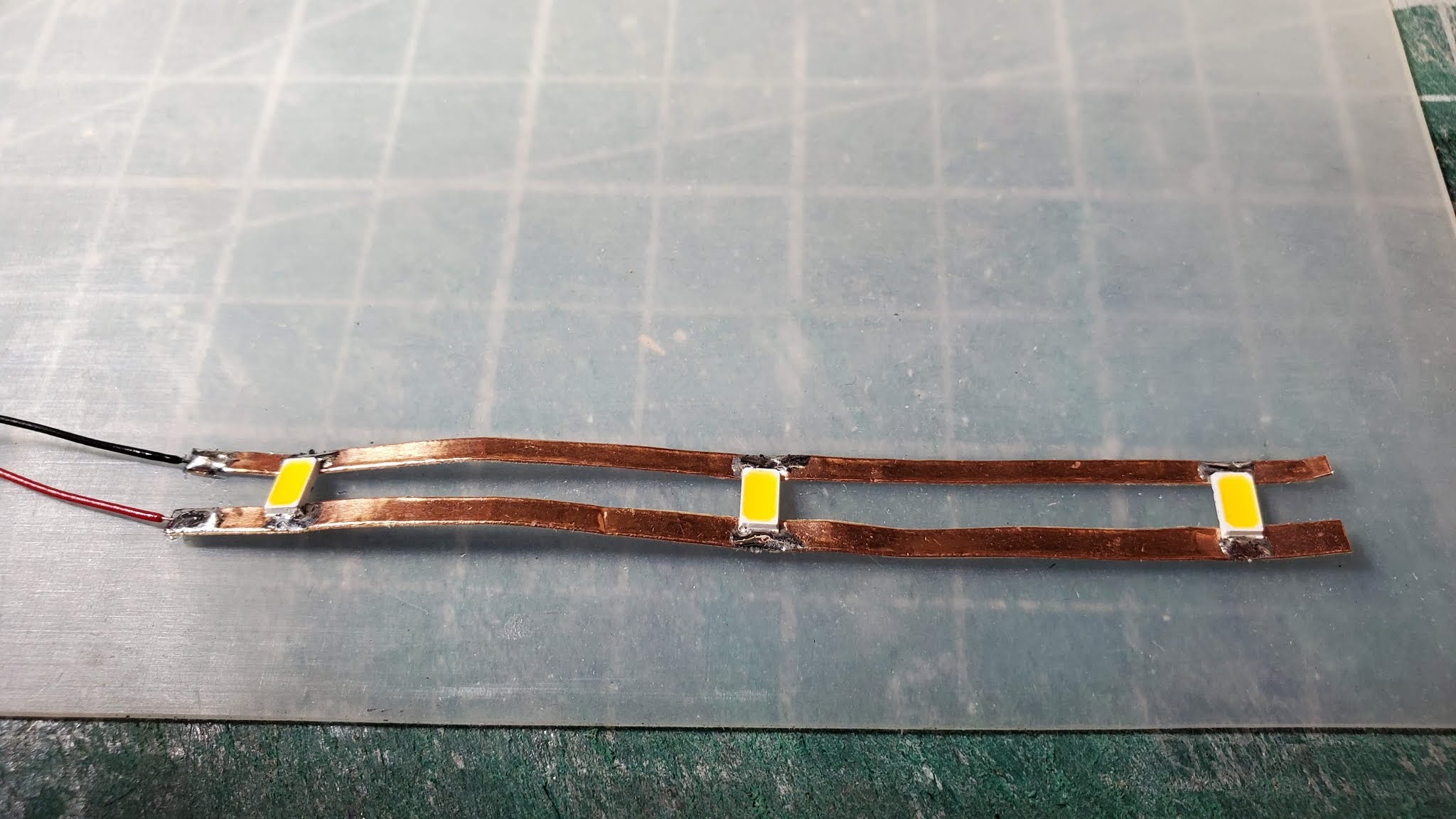
  9. from Hobby Lobby: 3/16 inch wide self-adhesive copper tape, sold as an accessory for making stained-glass windows (split in half down the middle and adhered to the underside of the car ceiling, with LEDs soldered between the strips)
  10. from eBay: 1/2 watt, 5630/5730 warm white high power LEDs (3 per car soldered to the above copper tape)
The principle behind this circuit is quite simple:
  1. Alternating current flows through the metal wheels and axles of the car (one end of each axle is insulated) and then through the piano wire "wipers" that rub against each axle. One truck takes power from one rail and the other truck from the other rail. This current is roughly 15 volts AC.
  2. The bridge rectifier converts the 15 volts AC into roughly 12 volts DC.
  3. The buck converter reduces the 12 volts DC to roughly 2.9 volts DC (MUST be lower than the 3-volt rating of the capacitor - if higher, the capacitor will overheat and explode)
  4. The 2.9 volts DC flows into both the supercapacitor and into the LED lighting mounted under the ceiling of the passenger car. With the resistor between the buck converter and the LEDs being rated higher than the resistor between the buck converter and the capacitor, the LEDs light as soon as power is applied but much of the current is diverted to the capacitor until it becomes fully charged, at which time all incoming power flows to the LEDs.
  5. When the connection is lost between the wheels and the rails, the capacitor slowly discharges its 2.9 volts to the LEDs, thus keeping the LEDs alight. If the track power is turned off or the car is lifted off the rails, the capacitor will power the LEDs for at least 20 seconds.
  6. It is important that the 10-ohm capacitor be included in this circuit. If such a resistor is absent the circuit will work. However, without the resistor, when the DCC system first powers the track there is such a huge inrush of power to all of the capacitors in the cars (I have 5 cars), the system interprets this as a short circuit and the system shuts down.

Here is a schematic of the circuit:


Here are pictures of the assembly process:

copper tape


tape cut lengthwise down middle (without cutting the paper backing)

rosin flux past applied to where LEDs and power wires to be connected 
copper tinned with solder where LEDs and power wires to be connected


tape cut all the way through
LEDs on the dispenser tape


LEDs showing front (left two) and back (right one - note the electrical contacts at each end); 9 volt battery is to show scale

LEDs and wire leads soldered to copper tape

testing to make sure LEDs light

beginning to remover paper backing from adhesive side of copper tape

starting the process of affixing to underside of roof

LEDs in place

drilling holes for #2-56 screws

electrical components (one of the two resistors is missing from the picture);  9-volt battery is only to show scale
 
electrical components (blue device on left is the supercapacitor and black device on right is bridge rectifier; both are soldered to the buck converter; the shiny metal disk near bottom edge of buck converter is a trim pot which is turned to adjust voltage output of buck converter)

the phosphor bronze sheet shaped to fit over the centre of the truck bolster, with hole for screw and piano wire fitted in place


wipers mounted in place

wipers mounted in place - top view


3D printed seats with passengers mounted in place; circuit components are housed in a compartment at the end of the car which has thin styrene walls - the white windows might be where the washrooms are located in the car

completed car on the track with lights on