Flicker-free Car Lighting

I am posting this on my favourite day of the year - Winter Solstice. Being the shortest day of the year, each day for the next 6 months gets progressively longer, an optimistic thought when one is in the dead of winter.

I own a set of vintage passenger cars that are well suited to a tourist excursion railway. On September 1, 2020, I posted final pictures of the Free-mo module I built this summer which depicts a tourist excursion railway so one of my next goals was to get my passenger cars ready for showtime.

Here are pictures of one of these cars:


As you can see, the interior is devoid of seats, passengers or lighting. It seems to me that whenever a passenger car is displayed on a model railroad, the absence of seats screams "incomplete". If there are seats, there should be at least a few passengers. The same principle applies to locomotives - many trains on model railroads are devoid of crew in the cab, which seems not only implausible but downright dangerous when the locomotive heads up a running train - but I digress.

Seating is easily accomplished by 3D printing a set of seats to fit the interior. HO scale people can easily be purchased. My challenge was lighting. I wanted to have flicker-free lighting powered by power from the rails. I had seen articles about how to build such a circuit, most recently on Larry Puckett's YouTube channel, The DCC Guy. I based my circuit on Larry's design with one exception. The articles always seem to include a diode in the circuit. However, it seemed to me that I could accomplish the same objective with the judicious selection of appropriately rated resistors.

The components include, per car:
  1. from eBay: phosphor bronze sheet, 0.1 mm thick (for contacts under the car)
  2. from a hobby shop: fine piano wire (also for contacts under the car)
  3. from my parts supply: #2-56 screws to pass from the underside of trucks into car body (to carry current to car interior)
  4. from Mouser: part number 625-DF01M-E3 bridge rectifier (to convert the AC power coming from the track to DC power)
  5. from eBay: LM2596 Mini 360 DC-DC buck converter step down module 4.75v - 23v to 1 v to 17v (to step down the DC voltage coming from the bridge rectifier to 2.9 volts)
  6. from Mouser: part number 581-SCCR12E105SRB 3 volt, 1-farad supercapacitor (to store the 2.9 volts of power coming from the buck converter and feed this voltage to the LED lighting in the car when track power is interrupted)
  7. from Digikey: part number CF14JT51R0TR-ND 51 ohm resistor (to protect the LEDs from over-voltage and also to adjust their brightness) [must be higher resistance than the following resistor]
  8. from Digikey: part number S10HTR-ND 10-ohm resistor (to prevent an inrush of current as the capacitor is charged when track power is turned on which, in turn, can cause a DCC system to interpret this as a short circuit)
  9. from Hobby Lobby: 3/16 inch wide self-adhesive copper tape, sold as an accessory for making stained-glass windows (split in half down the middle and adhered to the underside of the car ceiling, with LEDs soldered between the strips)
  10. from eBay: 1/2 watt, 5630/5730 warm white high power LEDs (3 per car soldered to the above copper tape)
The principle behind this circuit is quite simple:
  1. Alternating current flows through the metal wheels and axles of the car (one end of each axle is insulated) and then through the piano wire "wipers" that rub against each axle. One truck takes power from one rail and the other truck from the other rail. This current is roughly 15 volts AC.
  2. The bridge rectifier converts the 15 volts AC into roughly 12 volts DC.
  3. The buck converter reduces the 12 volts DC to roughly 2.9 volts DC (MUST be lower than the 3-volt rating of the capacitor - if higher, the capacitor will overheat and explode)
  4. The 2.9 volts DC flows into both the supercapacitor and into the LED lighting mounted under the ceiling of the passenger car. With the resistor between the buck converter and the LEDs being rated higher than the resistor between the buck converter and the capacitor, the LEDs light as soon as power is applied but much of the current is diverted to the capacitor until it becomes fully charged, at which time all incoming power flows to the LEDs.
  5. When the connection is lost between the wheels and the rails, the capacitor slowly discharges its 2.9 volts to the LEDs, thus keeping the LEDs alight. If the track power is turned off or the car is lifted off the rails, the capacitor will power the LEDs for at least 20 seconds.
  6. It is important that the 10-ohm capacitor be included in this circuit. If such a resistor is absent the circuit will work. However, without the resistor, when the DCC system first powers the track there is such a huge inrush of power to all of the capacitors in the cars (I have 5 cars), the system interprets this as a short circuit and the system shuts down.

Here is a schematic of the circuit:


Here are pictures of the assembly process:

copper tape


tape cut lengthwise down middle (without cutting the paper backing)

rosin flux past applied to where LEDs and power wires to be connected 
copper tinned with solder where LEDs and power wires to be connected


tape cut all the way through
LEDs on the dispenser tape


LEDs showing front (left two) and back (right one - note the electrical contacts at each end); 9 volt battery is to show scale

LEDs and wire leads soldered to copper tape

testing to make sure LEDs light

beginning to remover paper backing from adhesive side of copper tape

starting the process of affixing to underside of roof

LEDs in place

drilling holes for #2-56 screws

electrical components (one of the two resistors is missing from the picture);  9-volt battery is only to show scale
 
electrical components (blue device on left is the supercapacitor and black device on right is bridge rectifier; both are soldered to the buck converter; the shiny metal disk near bottom edge of buck converter is a trim pot which is turned to adjust voltage output of buck converter)

the phosphor bronze sheet shaped to fit over the centre of the truck bolster, with hole for screw and piano wire fitted in place


wipers mounted in place

wipers mounted in place - top view


3D printed seats with passengers mounted in place; circuit components are housed in a compartment at the end of the car which has thin styrene walls - the white windows might be where the washrooms are located in the car

completed car on the track with lights on


Automated Signals Using Arduino (Block Detection) - Part 2 of 2

In my last post, I described the operation of my Automated Block Signalling ("ABS") on my model railroad. In this post, I shall describe my method of building my own signal towers and I will share the complete Arduino code which runs the system.

I knew I was going to need a considerable number of operating signal towers, 10 for the upper level, 20 for the middle level (because it is double-track) and a few more for the lowest level. Searching online turned up a handful of vendors that sell operating signal towers and even fewer that sell the modern "Darth Vader" style which is becoming commonplace in the US and is being installed over time by Canadian Pacific which I model. Vendors typically have a small number in stock and pricing per-tower runs between $40 and $70 (Canadian dollars per head). I decided that I would set to work building my own.

Here are prototype images I took from the Internet:


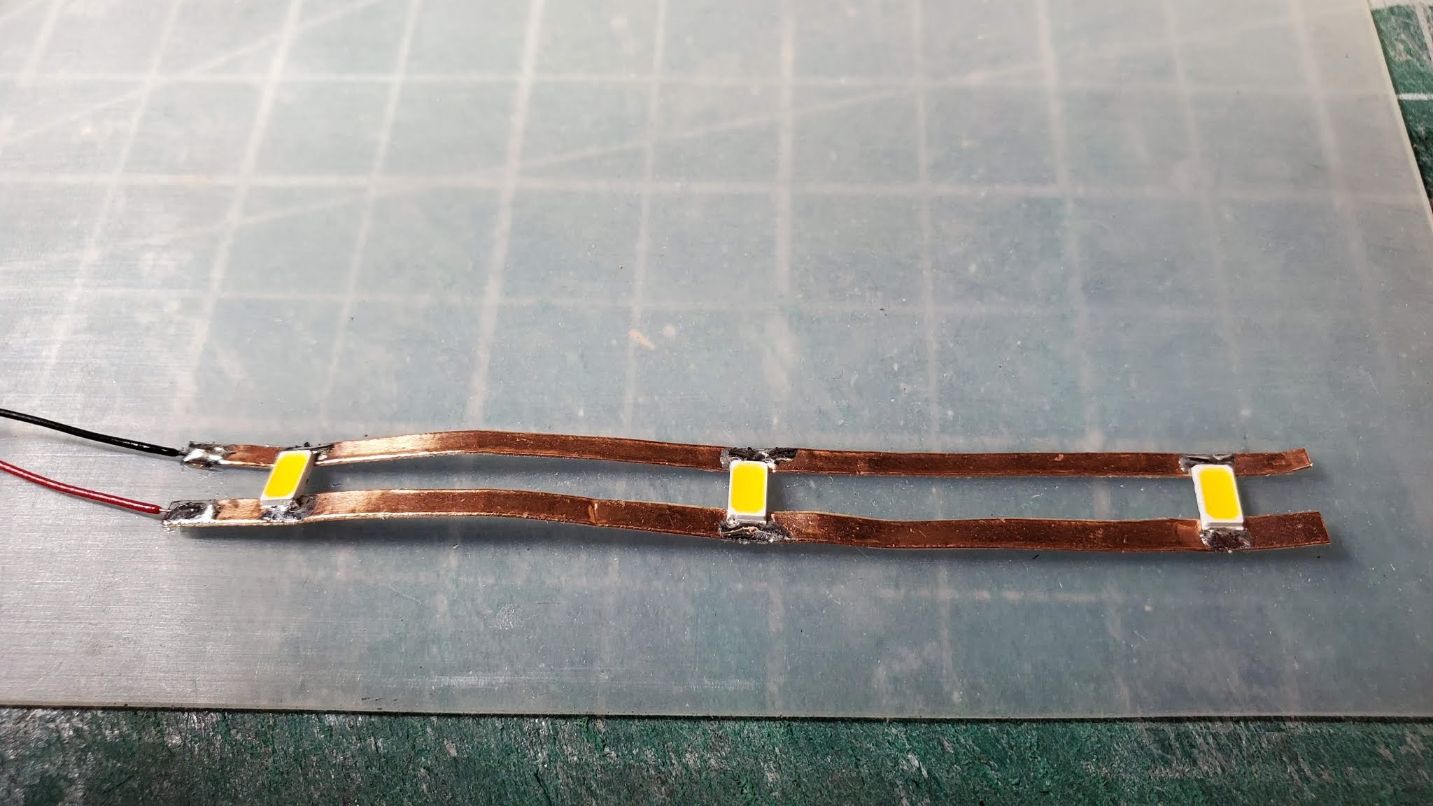
To build the signal "target" (the black contraption which contains the green, yellow and red signal lights) I used two thicknesses of sheet styrene 0.02 inches (for the flat shield which surrounds the lights) and 0.01 inches for the "Darth Vader" shroud.

I shall use pictures to show the steps I follow to make each signal head. I built a jig to make sure all of the parts are identical and to speed up production.

The brass insert with the three holes is where I drill the holes. The strip of 0.02 inch styrene is inserted underneath.


The drilled strip is inserted into a slot which is used to accurately cut the strip.

Unfortunately, the camera angle creates a trapezoidal illusion. The shape is actually rectangular.

The corners are carefully trimmed with an X-ACTO knife and then filed with a fine file.


Styrene 0.10 inches thick shaped for the "Darth Vader" hood before being curved.

Another jig used to bend the hood. A small dab of styrene cement is applied to the curved portion. This softens the material and, when dry, the styrene has taken on the curved shape. I find this much more reliable than applying heat which tends to melt and distort the thin styrene.

I made the shrouds much shallower than the prototype. This is because the prototype shroud is very deep to avoid signal light straying to the sides. The design allows the train crew to see the signal aspect but it is very difficult to see from an oblique angle. This is not practical for operating a model railroad because most of the time one's viewpoint is not directly down the track.


The completed shroud.

The completed signal head before being painted black.


I built several other jigs with which to make the signal tower. They are all mounted on one board (please note that there are some aspects of this board which are designed to build two-headed signal towers which will be the subject of a future blog post).

This board allows me to complete 8 steps of the construction process to ensure the level of precision needed so that the completed signal towers are as close as possible to being the same.

Green, yellow and red LEDs are inserted into this brass plate with the anode (positive side) facing away from the camera. They are all held in place by the toothpick which can be seen being inserted from the right.


Here an already-prepared mast has been inserted into the jig with an already-tinned brass strip touching the anodes of all three LEDs. The tip of a soldering iron is momentarily touched against the far side of the brass strip so the LEDs adhere to it. The excess LED legs are then trimmed so they are all flush with the top of the brass strip. The brass signal mast thus becomes the anode side of the circuit. Three 22 AWG wires (green, yellow and red) are then fed through the inside of the signal mast and soldered to the cathode side of the respective LEDs.

Note that there is a second brass strip on the other side which should be ignored for purposes of this discussion. This was there because at the time I was taking the photograph I was building a double-headed signal tower.


I 3D printed a ladder, two platforms that clip to the signal mast and three components that make up guard rails. This shows the items after being printed but before being separated from the "raft" and before plastic artifacts are trimmed away.


Two completed and operating signal towers in the foreground. The green signal changed to red in a fraction of a second after the picture was taken. Note the green signals in the distance indicating that the next blocks are unoccupied.


Note the red signal facing away from the locomotive and the green signal facing it.


Following is the complete Arduino code, 95% of which is Jimmy's from DIY and Digital Railroad on YouTube and 5% of which is my tweaks to modify some of the terminology so it was easier for me to understand the logic and also to change the behaviour of signal aspects when the signal turned from red to green.


int Sensor = 10; //Sensor is setup on Pin 10
int GreenLeft = 2; //Green Signal Facing Left on Pin 2 (used to be Green1)
int YellowLeft = 3;
int RedLeft = 4;
int GreenRight = 5; //Green Signal Facing Right on Pin 5 (used to be Green2)
int YellowRight = 6;
int RedRight = 7;//Sets up all of our separate signals on their pins
int BlockLeftSend = 8;//Sets up signal to be sent to previous block (used to be BlockASend)
int BlockRightSend = 9 ;//Sets up Signal to be sent to next block (used to be BlockBSend)
int BlockLeftRec = A0; //Sets up A0 as pin for receiving signal from previous block (used to be BlockARec)
int BlockRightRec = A1; //Sets up A1 as pin for receiving signal from next block(used to be BlockBRec)
int valA1 = 0;
int valA2 = 0;
int valA3 = 0;
int clearcount;

void setup() {
  Serial.begin(9600);

  //Establish all of our pins as inputs or outputs

  pinMode(Sensor, INPUT);
  pinMode(GreenLeft, OUTPUT);
  pinMode(YellowLeft, OUTPUT);
  pinMode(RedLeft, OUTPUT);
  pinMode(GreenRight, OUTPUT);
  pinMode(YellowRight, OUTPUT);
  pinMode(RedRight, OUTPUT);
  pinMode(BlockLeftSend, OUTPUT);
  pinMode(BlockRightSend, OUTPUT);
  pinMode(BlockLeftRec, INPUT);
  pinMode(BlockRightRec, INPUT);
}

enum SIGNALSTATES
{
  ST_GG,
  ST_GY,
  ST_YG,
  ST_YY,
  ST_RR,
  ST_YY1,
};//Sets up different signal states to switch to

SIGNALSTATES signalState = ST_GG;//GG is the default signal state

void loop() {
  valA1 = digitalRead(Sensor);//Reads Sensor
  valA2 = analogRead(BlockLeftRec);//Reads Block to left
  valA3 = analogRead(BlockRightRec);//Reads Bock to right
  delay(200);
  
  Serial.println("");
  Serial.print("valA1= ");
  Serial.println(valA1);
  Serial.print("valA2= ");
  Serial.println(valA2);
  Serial.print("valA3= ");
  Serial.println(valA3);  //Allows for values to be read on Serial Monitor
  delay(1);

  switch (signalState)
  {
    case ST_GG:
      signalgg(valA1, valA2, valA3);
      break;
    case ST_GY:
      signalgy(valA1, valA2, valA3);
      break;
    case ST_YG:
      signalyg(valA1, valA2, valA3);
      break;
    case ST_YY:
      signalyy(valA1, valA2, valA3);
      break;
    case ST_RR:
      signalrr(valA1, valA2, valA3);
      break;
    case ST_YY1:
      signalyy1(valA1, valA2, valA3);
      break;
      //This sets up our different loops within the main loop to switch between signal states
  }
}

void signalgg(int valA1, int valA2, int valA3) {
  digitalWrite(GreenLeft, LOW); //Turns Green facing Left On
  digitalWrite(YellowLeft, HIGH);
  digitalWrite(RedLeft, HIGH);
  digitalWrite(GreenRight, LOW); //Turns Green facing Right On
  digitalWrite(YellowRight, HIGH);
  digitalWrite(RedRight, HIGH);
  digitalWrite(BlockLeftSend, LOW); //No signal from this block
  digitalWrite(BlockRightSend, LOW); //No signal from this block
  Serial.println("No Train");//Allows text to be seen in serial monitor
  delay(1);
  clearcount = 0;

  if ((valA1 > 0) && (valA2 < 750) && (valA3 > 750)) {
    signalState = ST_GY;//Block clear but Block to Right occupied
  }
  if ((valA1 > 0) && (valA2 > 750) && (valA3 < 750)) {
    signalState = ST_YG;//Block clear but Block to Right occupied
  }
  if ((valA1 > 0) && (valA2 > 750) && (valA3 > 750)) {
    signalState = ST_YY;//Block clear but Blocks to Left and Right are occupied
  }
  if (valA1 < 1) {
    signalState = ST_RR;//Block occupied
  }
}
void signalgy(int valA1, int valA2, int valA3) {
  digitalWrite(GreenLeft, LOW); //Turns Green facing Left On
  digitalWrite(YellowLeft, HIGH);
  digitalWrite(RedLeft, HIGH);
  digitalWrite(GreenRight, HIGH);
  digitalWrite(YellowRight, LOW);// Turns Yellow facing Righ On
  digitalWrite(RedRight, HIGH);
  digitalWrite(BlockLeftSend, LOW); //No signal from this block
  digitalWrite(BlockRightSend, LOW); //No signal from this block
  Serial.println("Approach with Caution");//Allows text to be seen in serial monitor
  delay(1);


  if ((valA1 > 0) && (valA2 < 750) && (valA3 < 750)) {
    signalState = ST_GG;//Block clear
  }
  if ((valA1 > 0) && (valA2 > 750) && (valA3 < 750)) {
    signalState = ST_YG;//Block clear but Block to Right occupied
  }
  if ((valA1 > 0) && (valA2 > 750) && (valA3 > 750)) {
    signalState = ST_YY;//Block clear but Blocks to Left and Right are occupied
  }
  if (valA1 < 1) {
    signalState = ST_RR;//Block occupied
  }
}
void signalyg(int valA1, int valA2, int valA3) {
  digitalWrite(GreenLeft, HIGH);
  digitalWrite(YellowLeft, LOW);//Turns Yellow facing Left On
  digitalWrite(RedLeft, HIGH);
  digitalWrite(GreenRight, LOW); //Turns Green facing Right On
  digitalWrite(YellowRight, HIGH);
  digitalWrite(RedRight, HIGH);
  digitalWrite(BlockLeftSend, LOW); //No signal from this block
  digitalWrite(BlockRightSend, LOW); //No signal from this block
  Serial.println("No Train Ahead");//Allows text to be seen in serial monitor
  delay(1);


  if ((valA1 > 0) && (valA2 < 750) && (valA3 > 750)) {
    signalState = ST_GY;//Block clear but Block to Left occupied
  }
  if ((valA1 > 0) && (valA2 < 750) && (valA3 < 750)) {
    signalState = ST_GG;//Block clear
  }
  if ((valA1 > 0) && (valA2 > 750) && (valA3 > 750)) {
    signalState = ST_YY;//Block clear but Blocks to Left and Right are occupied
  }
  if (valA1 < 1) {
    signalState = ST_RR;//Block occupied
  }
}
void signalyy(int valA1, int valA2, int valA3) {
  digitalWrite(GreenLeft, HIGH);
  digitalWrite(YellowLeft, LOW);//Turns Yellow facing Left On
  digitalWrite(RedLeft, HIGH);
  digitalWrite(GreenRight, HIGH);
  digitalWrite(YellowRight, LOW);//Turns Yellow facing Right On
  digitalWrite(RedRight, HIGH);
  digitalWrite(BlockLeftSend, LOW); //No signal from this block
  digitalWrite(BlockRightSend, LOW); //No signal from this block
  Serial.println("No Train");//Allows text to be seen in serial monitor
  delay(1);


  if ((valA1 > 0) && (valA2 < 750) && (valA3 > 750)) {
    signalState = ST_GY;//Block clear but Block to Left occupied
  }
  if ((valA1 > 0) && (valA2 > 750) && (valA3 < 750)) {
    signalState = ST_YG;//Block clear but Block to Right occupied
  }
  if ((valA1 > 0) && (valA2 < 750) && (valA3 < 750)) {
    signalState = ST_GG;//Block clear but Blocks to Left and Right are occupied
  }
  if (valA1 < 1) {
    signalState = ST_RR;//Block occupied
  }
}
void signalrr(int valA1, int valA2, int valA3) {
  digitalWrite(GreenLeft, HIGH);
  digitalWrite(YellowLeft, HIGH);
  digitalWrite(RedLeft, LOW);//Turns Red facing Left On
  digitalWrite(GreenRight, HIGH);
  digitalWrite(YellowRight, HIGH);
  digitalWrite(RedRight, LOW);//Turns Red facing Right On
  digitalWrite(BlockLeftSend, HIGH); //signal from this block
  digitalWrite(BlockRightSend, HIGH); //signal from this block
  Serial.println("Block is Occupied");//Allows text to be seen in serial monitor
  delay(1);

  if (valA1 > 0) {
    signalState = ST_YY1; //switches over to the transition yellow signal state
  }
}

void signalyy1(int valA1, int valA2, int valA3) {
  digitalWrite(GreenLeft, HIGH);
  digitalWrite(YellowLeft, LOW);//Turns Yellow facing Left On
  digitalWrite(RedLeft, HIGH);
  digitalWrite(GreenRight, HIGH);
  digitalWrite(YellowRight, LOW);//Turns Yellow facing Right On
  digitalWrite(RedRight, HIGH);
  digitalWrite(BlockLeftSend, HIGH); //signal from this block
  digitalWrite(BlockRightSend, HIGH); //signal from this block
  Serial.println("Train just left block");//Allows text to be seen in serial monitor
  delay(1);

  if ((valA1 > 0) && (clearcount < 5)) {
    clearcount++;
  }
  else if ((valA1 < 1) && (clearcount < 5)) {
    clearcount = 0; //checks for false positives of clear track
  }
  else if ((valA1 > 0) && (clearcount > 4)) {
    signalState = ST_YY;//goes to signal state YY where occupancy status is checked
  }
}

Automated Signals Using Arduino (Block Detection) - Part 1 of 2

For some time I have wanted to install Automated Block Signalling ("ABS") on my model railroad.

From Wikipedia, the definition of ABS is: "a railroad communications system that consists of a series of signals that divide a railway line into a series of sections, or "blocks". The system controls the movement of trains between the blocks using automatic signals. ABS operation is designed to allow trains operating in the same direction to follow each other in a safe manner without risk of rear-end collision."

Following is a graphic depicting how an ABS system works.


There are several such systems on the market which are available for purchase. I find that these are either more than I am willing to pay or more complex than what I had in mind. Since I have had good experiences with the use of Arduino microcontrollers I had been thinking about how to design my own ABS using Arduinos. My biggest stumbling block was how to have one Arduino communicate to another and vice versa. All the methods I could find descriptions of were difficult for me to understand.

A few months ago I subscribed to a YouTube channel called DYI and Digital Railroad which is hosted by a personable fellow whose first name is Jimmy. Jimmy posted a video describing exactly what I was looking for. Here is a link to Jimmy's video (thank you Jimmy)  DIY Arduino Model Railroad Multiple Block Signal System. He also posted the complete Arduino code that he used to power all of the interconnected Arduinos, each of which controlled the signals which protect a block of the track by lighting the appropriate signals at each end of the block.

As can be seen in the above simple graphic, the train is located in the block which shows it is "Occupied". The signal facing to the rear of the train (which would be seen by the engineer of a train following) turns red, protecting the block against encroachment by the following train. When the Arduino changes the signal state to red it tells the Arduino to its left that it has done so. The Arduino to the left changes its signal state to yellow which cautions an approaching train that the block which is two ahead is occupied.

Each Arduino actually controls two signal towers, one facing out from the left of the block and the other facing out from the right of the block (not drawn in the above diagram). This ensures protection for each block in each direction. Each Arduino communicates to both adjacent Arduinos which control the adjacent blocks.

The "out" signal to both adjacent Arduinos is sent using digital pins. It is read using analog inputs by the adjacent Arduinos. The digital output is either "on" or "off" and is read by the adjacent Arduinos as having a value of 1,023 (can be lower because of line losses, signal noise, etc.).

Jimmy's presentation introduced me to a device made by the Digital Command Control ("DCC") system manufacturer NCE. The device, called a BD-20, can be installed very easily in an existing layout by making a fine cut in one of the rails at each end of the block for which you wish to detect the presence of a train. The wire which feeds this rail is looped through the sensing ring mounted on the top of the BD-20.

The BD-20 is powered with 12 volt DC and has a "logic" terminal which is connected to the appropriate Arduino input pin.

When a locomotive or other rolling stock that draws current occupies the block the BD-20 will communicate the occupancy to the Arduino.

Here is a graphic depiction of the key attributes of the setup:


In Part 2 of this post I shall explain how I built my own signal heads. I will also share the complete Arduino code - I tweaked Jimmy's code somewhat to overcome a couple of small shortcomings.