Following is how I addressed each of my design criteria when sitting down to determine how to construct my two-level lift gate:
Criteria 1: "Both gates must lift and lower simultaneously."
I knew that this would likely be the most difficult part of the design because of the linkage that was required between the top and bottom gates. Algodoo is a free software program that is very handy for working out physics problems. The program can be downloaded here: http://www.algodoo.com/. With Algodoo you can design a mechanism and then operate it to determine whether the design will work. It uses the laws of physics and geometry. I have only scratched the surface but it is possible to adjust the environment in the program to mimic gravity, wind, momentum, friction, etc.
Here are two screenshots of my mechanism in Algodoo which shows the basic design of the gates in both the open and closed positions:
 |
| Gates (coloured turquoise) in the closed position. |
Criteria 2: "Resistance to the force of gravity."
The "spring" in the above diagrams is actually a pair of "Soft-Open/Close Gas Spring Drop-Dow Stays" from Lee Valley (part number 00T0247) https://www.leevalley.com. These provide resistance when the piston is pushed into or pulled out of the housing, unlike a gas spring which acts like a spring under compression. In other words, it acts as a damper. The Drop-Down Stays provide no push or pull force when they are not being moved in or out of the housing. By installing these under the fulcrum of the lower gate, considerable resistance is applied to the gate when it drops, allowing it to close gently after being given a gentle nudge to free the grasp of the top of the gate from the permanent magnet mounted on the ceiling-mounted lighting valence.
This is what they look like:
Criteria 3: "Flawless alignment of rails."
I used two features to ensure that the rails are always in alignment:
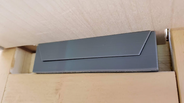
- If the gates are always in alignment this will go a long way to ensuring that the rails are also in alignment. I 3D printed two nesting parts, one of which is attached to the underside of the gate (the "male" part) where it inserts into the other part mounted on the vertical upright (the "female" part). A picture is worth a thousand words:
 |
| The upper "male" part resting in the lower "female" part. |
These 3D printed parts ensure that each gate is guided into position without any lateral movement.


