I am posting this on my favourite day of the year - Winter Solstice. Being the shortest day of the year, each day for the next 6 months gets progressively longer, an optimistic thought when one is in the dead of winter.
I own a set of vintage passenger cars that are well suited to a tourist excursion railway. On September 1, 2020, I posted final pictures of the Free-mo module I built this summer which depicts a tourist excursion railway so one of my next goals was to get my passenger cars ready for showtime.
Here are pictures of one of these cars:
As you can see, the interior is devoid of seats, passengers or lighting. It seems to me that whenever a passenger car is displayed on a model railroad, the absence of seats screams "incomplete". If there are seats, there should be at least a few passengers. The same principle applies to locomotives - many trains on model railroads are devoid of crew in the cab, which seems not only implausible but downright dangerous when the locomotive heads up a running train - but I digress.
Seating is easily accomplished by 3D printing a set of seats to fit the interior. HO scale people can easily be purchased. My challenge was lighting. I wanted to have flicker-free lighting powered by power from the rails. I had seen articles about how to build such a circuit, most recently on Larry Puckett's YouTube channel, The DCC Guy. I based my circuit on Larry's design with one exception. The articles always seem to include a diode in the circuit. However, it seemed to me that I could accomplish the same objective with the judicious selection of appropriately rated resistors.
The components include, per car:
- from eBay: phosphor bronze sheet, 0.1 mm thick (for contacts under the car)
- from a hobby shop: fine piano wire (also for contacts under the car)
- from my parts supply: #2-56 screws to pass from the underside of trucks into car body (to carry current to car interior)
- from Mouser: part number 625-DF01M-E3 bridge rectifier (to convert the AC power coming from the track to DC power)
- from eBay: LM2596 Mini 360 DC-DC buck converter step down module 4.75v - 23v to 1 v to 17v (to step down the DC voltage coming from the bridge rectifier to 2.9 volts)
- from Mouser: part number 581-SCCR12E105SRB 3 volt, 1-farad supercapacitor (to store the 2.9 volts of power coming from the buck converter and feed this voltage to the LED lighting in the car when track power is interrupted)
- from Digikey: part number CF14JT51R0TR-ND 51 ohm resistor (to protect the LEDs from over-voltage and also to adjust their brightness) [must be higher resistance than the following resistor]
- from Digikey: part number S10HTR-ND 10-ohm resistor (to prevent an inrush of current as the capacitor is charged when track power is turned on which, in turn, can cause a DCC system to interpret this as a short circuit)
- from Hobby Lobby: 3/16 inch wide self-adhesive copper tape, sold as an accessory for making stained-glass windows (split in half down the middle and adhered to the underside of the car ceiling, with LEDs soldered between the strips)
- from eBay: 1/2 watt, 5630/5730 warm white high power LEDs (3 per car soldered to the above copper tape)
The principle behind this circuit is quite simple:
- Alternating current flows through the metal wheels and axles of the car (one end of each axle is insulated) and then through the piano wire "wipers" that rub against each axle. One truck takes power from one rail and the other truck from the other rail. This current is roughly 15 volts AC.
- The bridge rectifier converts the 15 volts AC into roughly 12 volts DC.
- The buck converter reduces the 12 volts DC to roughly 2.9 volts DC (MUST be lower than the 3-volt rating of the capacitor - if higher, the capacitor will overheat and explode)
- The 2.9 volts DC flows into both the supercapacitor and into the LED lighting mounted under the ceiling of the passenger car. With the resistor between the buck converter and the LEDs being rated higher than the resistor between the buck converter and the capacitor, the LEDs light as soon as power is applied but much of the current is diverted to the capacitor until it becomes fully charged, at which time all incoming power flows to the LEDs.
- When the connection is lost between the wheels and the rails, the capacitor slowly discharges its 2.9 volts to the LEDs, thus keeping the LEDs alight. If the track power is turned off or the car is lifted off the rails, the capacitor will power the LEDs for at least 20 seconds.
- It is important that the 10-ohm capacitor be included in this circuit. If such a resistor is absent the circuit will work. However, without the resistor, when the DCC system first powers the track there is such a huge inrush of power to all of the capacitors in the cars (I have 5 cars), the system interprets this as a short circuit and the system shuts down.
Here is a schematic of the circuit:
Here are pictures of the assembly process:
 |
| copper tape |
 |
| tape cut lengthwise down middle (without cutting the paper backing) |
 |
| rosin flux past applied to where LEDs and power wires to be connected |
 |
| copper tinned with solder where LEDs and power wires to be connected |
 |
| tape cut all the way through |
 |
| LEDs on the dispenser tape |
 |
| LEDs showing front (left two) and back (right one - note the electrical contacts at each end); 9 volt battery is to show scale |
 |
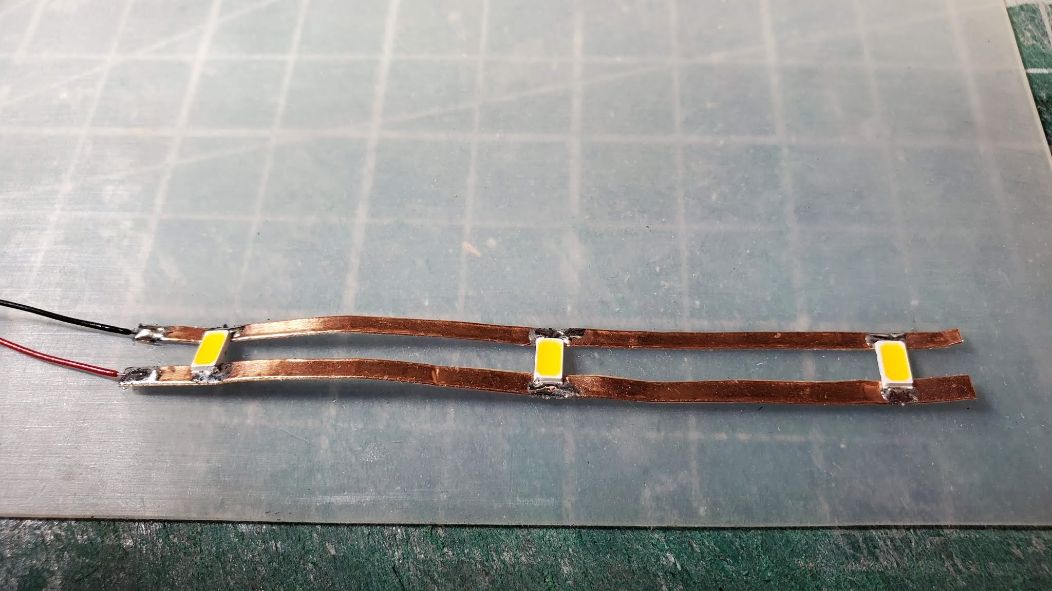
| LEDs and wire leads soldered to copper tape |
 |
| testing to make sure LEDs light |
 |
| beginning to remover paper backing from adhesive side of copper tape |
 |
| starting the process of affixing to underside of roof |
 |
LEDs in place
|
 |
drilling holes for #2-56 screws
|
 |
| electrical components (one of the two resistors is missing from the picture); 9-volt battery is only to show scale |
 |
electrical components (blue device on left is the supercapacitor and black device on right is bridge rectifier; both are soldered to the buck converter; the shiny metal disk near bottom edge of buck converter is a trim pot which is turned to adjust voltage output of buck converter)
|
 |
the phosphor bronze sheet shaped to fit over the centre of the truck bolster, with hole for screw and piano wire fitted in place
|
 |
wipers mounted in place
|
 |
wipers mounted in place - top view
|
 |
3D printed seats with passengers mounted in place; circuit components are housed in a compartment at the end of the car which has thin styrene walls - the white windows might be where the washrooms are located in the car
|
 |
completed car on the track with lights on
|


