Construction of Steel Bins

My last post outlined the construction of the main office for Okanagan Seed & Feed. This business needs to be served by both rail and road. The railway will deliver bulk seed and feed components and will also pick up seed and feed components for customers. Trucks will also be able to take loads.

I had on my shelf the following plastic kit made by Rix Products. This includes all required parts EXCLUDING the bins themselves which I did not have on hand. However, judging by the picture the diameter of the bins would be too large for the available space on my layout so I needed to make my own.


I first decided on the dimensions (6 cm diameter and 15 cm high to the lip of the roof; about 2.4 inches by 5.9 inches) and sketched them out on 0.020 styrene sheets, cutting carefully so all edges were true.

I made three styrene disks to fit inside the bin, one each near the top, bottom and middle to provide some structural integrity. It turned out that my diameter was very slightly larger than that of a stack of pan pastel chalks, so I carefully wrapped the styrene sheet that will become the side walls around the pan pastels, as follows:


I next clamped the material as shown below and applied a thin bead of styrene cement to those places between the disk and sidewall only where they touch. I let this completely dry before proceeding to the next step.


I next used rubber bands, assisted by slight pressure from a clamp (clamp not shown below) to complete wrapping the side walls around the disk. Styrene cement was applied to complete the circle. I did this in two steps because to do it all at once was like watching a one-armed wallpaper hanger in action!


Once the adhesive had set I slid the pan pastels out from the bottom and inserted the middle internal styrene disk and glued it in place. Finally, I glued the internal styrene disk inside the other end (no pictures of these steps).

Next I used a compass to draw a styrene disk which became the roof. I carefully cut a pie-shaped slice out of the disk.


I then clamped this together so the edges butted and applied styrene adhesive, as follows:


I next glued the roof to the top of the bin, holding it in place with rubber bands for the adhesive to set:


I next added this detail, a clean-out hatch:


And ribs for the roof:


I then sprayed the top and around the cleanout hatch with Krylon silver metallic spray paint. Krylon is my favourite spray paint because it dries in 10 minutes with much less smell than other brands. I still use a full respirator and a paint booth which is vented outside because this stuff is hardly organic - your first clue is the skull and crossbones warning label on the can!


For the corrugated steel exterior I used a product that I purchased several years ago called Brunel Models Corrugated Iron Maker. This is HO scale but they do sell it for other scales. This little plastic device has two parts as shown below - a base and a smaller piece, both of which have very fine grooves machined in their surfaces. Aluminum foil is placed on the base and the smaller component is dragged smoothly across the foil. This produces a very nice scale facsimile of corrugated iron or steel. The following photograph shows a strip with many such corrugated panels. These are then cut to size and glued to your project. Tip: Brunel Models sells aluminum foil which they claim is more robust than ordinary kitchen foil. I have tried both and find that the ordinary kitchen foil works just as well.


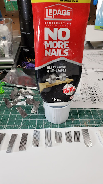
Because I was fastening metal foil to styrene I did some experiments to determine the best adhesive to attach the panels. The adhesive needed to be very sticky yet dry clear and be strong enough that the panels would not peel off. I settled on one of my favourite adhesives, No More Nails by Lepage as seen here:

Here is a picture of a partially-completed bin:


I next painted the entire bin with the silver metallic Krylon spray paint because I wanted a uniform metallic colour for this structure which, after all, would be a uniform colour in real life:


I wanted to weather my bins to represent fairly significant ageing, with quite a lot of old rust on the roof and rust on the siding, exacerbated where there were imperfections caused by dents. I used a technique that I had read about in Model Railroad Hobbyist Magazine, one of my favourites. This was described in the What's Neat section of the February 2018 edition on pages 2 through 5. First acrylic burnt umber paint is applied to areas where there would be heavy "old" rust. Let this dry thoroughly before proceeding to the next step. Next, using burnt sienna OIL paint apply to areas where there would be newer rust. Apply a little paint thinner or Turpenoid to the oil paint to make it "bleed". The acrylic paint is not affected by the application of oil paint or paint thinner because the two substances are not compatible.

Here is a picture of a partially painted roof with the acrylic burnt umber:


Here is a picture of the same roof after the application of the oil burnt sienna after it has bled with Turpenoid and blotted slightly with a shop towel to remove excess paint:


Finally, this is the overall effect. Note that I also added some rust effects to the exterior walls, with extra rust where the panels have been dented:


All of the above steps provide for the train unloading and loading facility. I now needed to add a truck loading facility. I had on hand what had been designed as a wood chip loader from the Walthers Sawmill Outbuildings kit. I had not yet used this structure anywhere and decided that I could easily repurpose it as a truck loading device for feed and seed.

This is a picture of the kit that this device came from:


Here is the truck loading device added to the previous project:


Finally, a close-up shot of the finished project:


Next up ...... finishing the scenicing of the surrounding lands.


Craftsman Kit - Sandy & Pyne Cabinetmakers

Several years ago I purchased a craftsman kit from Rusty Stumps Scale Models called Sandy & Pyne Cabinetmakers. This HO scale kit depicts a two-storey wooden structure with some interesting design features. On my home layout I have been working on a couple of industries for the Kelowna, British Columbia area. I decided that I could rename the business Okanagan Seed & Feed to be used in my scene.

This kit was very well packaged and the instructions very good, describing in great detail what to do at every stage. It came with all required components except of course for paint, stain and adhesives. I decided to add a basic interior to the lower level as well as lighting. If you are looking for this kit you will have to find one that someone has sitting on a shelf at home or in a hobby shop or perhaps on eBay because Rusty Stumps no longer produces craftsman kits. The owners are getting fairly elderly and are concentrating on making 3D printed details.

This is a picture of the partially completed structure along with the assembly manual. You can see a bit of the lower level interior which consists of a colour photograph of packages on shelves. I created a cardboard triangle that fit between the floor and ceiling and glued the photograph so it appears on all sides of the triangle. If guests peers through one of the downstairs windows they spot the shelving and quickly conclude that the interior has been completed furnished. The lighting consists of two warm white LEDs fastened to the underside of the ceiling.


Here are some pictures of the completed structure. This was a very enjoyable project.

In the above picture, you can see one of the wires from underneath the structure that will be connected to 12 volt DC power for the building lighting.


Weathering Effect - Peeling Paint

I have read about several different techniques to give the effect of peeling paint on a building or other structure. My preferred technique employs hair spray - any will do but I prefer the low odour variety for the sake of my nose.

The first step is to ensure that the surface, whether plastic or wood, is free of dust, dirt and oil. The model I shall use for the pictures below is a styrene plastic kit, the Walthers Cornerstone Walton & Sons Lumber Company kit.

Next, decide what colour you would like to show through from behind the peeling paint. Normally a grey to beige colour would be appropriate if you are weathering a "wood" structure. If you are weathering a "steel" building then the colour would be whatever metal or primer would be plausibly showing through the peeling paint.

When selecting a colour, I suggest doing a test piece. I once decided that a medium grey colour would be appropriate to show through the peeling paint. The top coat of paint was brown. When the top coat was peeled away the grey underneath looked like royal blue against the brown which was rather off-putting.

In the case of the Walton & Sons Lumber Company kit I decided that the colour of the styrene was an appropriate colour to show through the yellow paint finish.

After ensuring that the completed building (without any window glass or roof installed) was free of dirt and grease I applied a coat of hair spray to the walls and let it completely dry. I then used my airbrush to apply the topcoat of paint, an acrylic light yellow. I let this dry overnight. Here is a picture of the completed wall, up close:


Using a medium bristle paintbrush I carefully painted water selectively where I wanted the paint to peel off. After a few seconds of being wet, the topcoat of yellow paint softens considerably and the moisture soaks through to the hair spray which is water-soluble. This makes the paint very easy to flake off. Don't be too aggressive at first until you get the hang of it.

Here are a couple of pictures which show the effect. You might note the white styrene strip with fine wires running lenghtwise. This is for the LEDs which are used to light the building.


Next I applied an even coast of clear matte spray. I really like the Krylon spray for this as it truly is low odour as it claims to be. As with all Krylon spray paint it also dries much faster than others I have tried. I used my paint booth and a respirator because, as will all spray paints (including an airbrush with acrylic paint) this is a foreign substance which is not good for your lungs or brain.


I next applied a dusting of white weathering chalk to tone down the paint colour to make it look as if has been exposed to the elements for a number of years. After all, paint peeling normally takes place after paint has been weathered for several years.


Here are a few other pictures:


I like this technique for creating a peeling paint effect.


Automated Signals for Free-mo (Infrared Detection) - Part 3 of 3

Here is the wiring to take the signals from the infrared sensors under each track and also to power the dual signal heads:


I am pleased to report that the system works as designed. Here is a shot of the signal masts:


These masts are mounted on one of the Free-mo modules in my basement layout. I have yet to build any individual dedicated Signal-mos. Once I have done so I shall post pictures.

Automated Signals for Free-mo (Infrared Detection) - Part 2 of 3

 Other components of my signalling system include:

Signal Masts

As with my last signal project described in December, I again made my own signal masts using the same jig described at that time. However, as can be seen in the above picture each mast is double-headed to accommodate signalling in both directions (in my earlier project I used two separate single-headed masts to control traffic in each direction). Since this project is signalling for double-track Free-mo mainline I need signals for both directions for each track so double-headed signals made for less complexity.

Unlike my earlier signalling project for which the signal masts are permanently mounted on the layout, for the Free-mo signals, I wanted a method of making the signal masts removable so they can be stored and transported separately from the Signal-mo modules to lessen the chance of damage.

In the above picture, the grey-coloured base was 3D printed with snug-fitting mounts on which the signal towers fit. The box with the green, yellow and red stripes fits over the signal masts and is fastened shut with Velcro.

Signal Mast Mounts


The grey component is 3D printed to accept a 10-pin female receptacle.


The above picture shows the receptacle mounted in a module. It is fastened with screws from the underside. The bottom of each signal mast has a 3D printed base in which is mounted a male 10-pin connector which plugs into this female base.


Here is a signal mast mounted on the base.

The 10-pin connectors at the bottom of each signal mast are wired as follows:


The red, yellow and green connectors on the left are wired to the three corresponding colour LEDs facing one direction. The other red, yellow and green connectors are wired to the LEDs facing the other direction. The two white connectors are wired to the shaft of the signal mast which is made of brass. The anodes of all the LEDs are wired to the mast. It is important to note that different colours of LEDs draw different amounts of current. Therefore, in order to ensure a comparable brightness of all LEDs I did a bit of experimentation and wired different strength resistors in the wires to each of the different colour LEDs.

The wiring configuration described above means that it doesn't matter which way around a signal mast is mounted - the same contacts will light the same LED colours regardless of which way around the signal mast is mounted.

IR Detector Mounting

My last blog post described the infrared detectors that are to be mounted between the rails. These need to be mounted in place.


The two receptacles for the signal masts are made to fit in a 3/4 inch hole. The holes between the rails for the IR sensors were made using the high-speed hole saw pictured above.


I 3D printed the above fixture which is used to hold the IR sensors in place from beneath the module.


The picture above shows the two signal tower receptacles mounted under the module on the extreme left and the right of the picture and the two IR sensors mounted in the middle. The wires at the bottom of the picture have nothing to do with this project.


I put a thin layer of Flex Paste around the IR emitter and sensor. Flex Paste is one of the "Flex Family of Products" advertised by that very annoying man on TV. What I like about it for this application is, by soaking a Q-tip in isopropyl alcohol one can easily remove excess material and smooth the leftover surface.


This shows all components mounted in the module. I still need to add some ballast to cover the white Flex Paste. When this picture was taken the IR emitter was powered up - you can tell because a digital camera is sensitive to infrared light (tip - if you want to see the infrared signals coming from any such emitter, such as a TV remote control, simply turn on the camera in your smartphone and point it at the output window of the remote and active the remote control button - very handy if you aren't sure whether the remote isn't working only because of a dead battery or because you dropped and broke it!).